Section 2: Overview 2-13
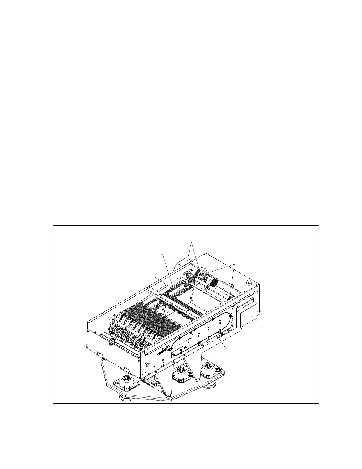
String Wagon And Drive Assembly
The String Wagon moves back and forth in the main frame to lower or raise the pins and to lift and
lower the gate. The wagon is driven clockwise using a chain attached to the Motor and Gear Assembly.
Fins mounted inside the main frame guide the strings front to back keeping them separated so they
don’t interfere with each other.
When going toward the front of the machine (Home Position), the strings are let out to allow pins to
lower to the pindeck. Adjustable brackets called Slow Setting Pin brackets ensure that the pins are set
smoothly on the pindeck. Whether the pin is actually lowered is determined by a string brake located in
the Pin Motion Interface.
As the wagon returns to the rear of the machine, the strings are pulled back causing the pins to lift into
the centering cones located on the setting platform.
If pins are unable to lift into the center cones due to a string tangle, the added tension on the strings
trigger a De-tangling Bar and Switch. The machine will attempt to untangle the strings by continually
turning the drive motor o, then on, to create a up/down shaking motion of the pins. Switches inside the
Cam and Switch Cluster assembly are used to monitor the location of the string wagon.
Stop Dogs hold the sweep wagon at the back of the machine in the “pins up” position. Although they
are not used during normal machine operation, the blocks are needed to prevent the weight of the pins
from pulling the wagon to the front of the machine after the “Pins Up” switch is pressed. Having the
wagon held in this position is useful when performing maintenance functions such as string tensioning.
Refer to Fig ure 2-13.
(3)
STOP
DOGS
(1)
CHAIN
TRACK
(5)
STRING
WAGON
(6)
CHAIN
ROTATION
MOTOR AND GEAR
ASSEMBLY
(4)
CAM AND
SWITCH CLUSTER
Figure2-13.StringWagonDriveComponents
(1) CHAIN TRACK (2) MOTOR AND GEAR (3) STOP DOGS
A SSEM BLY
(4) CAM AND SWITCH CLUSTER (5) STRING WAGON (6) CHAIN ROTATION