Section 2: Overview 2-19
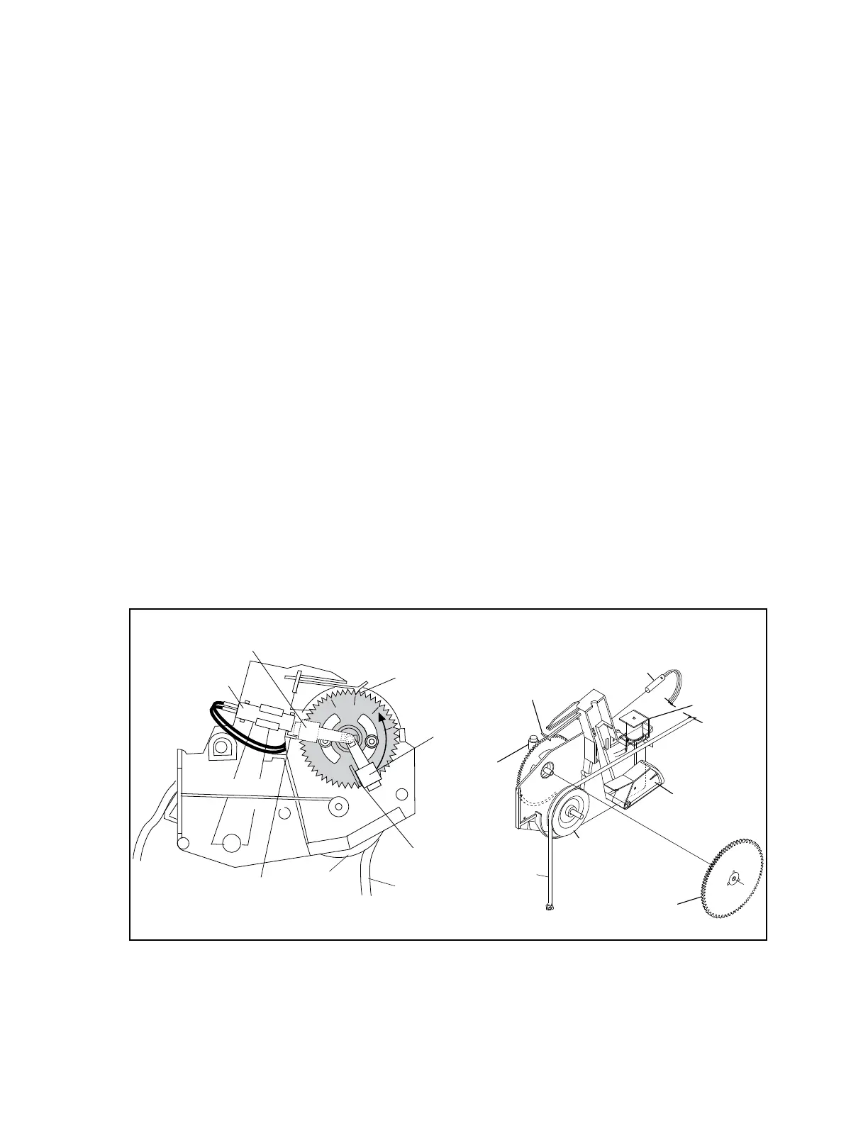
Pin Motion Interface (PMI)
The Pin Motion Interface is the nal main frame component a string passes through before being routed
to the setting platform and pin. The Pin Motion Interface serves two main functions for the pinsetter.
1. Detects when a pin has been knocked over.
2. Controls whether the pin will be lowered to the pindeck when the string wagon
moves toward the front of the machine.
When a pin is knocked over, the pulling of the string causes a pulley and gear, referred to as a string
roller and string gear, to rotate. If the string pulls with enough force, a magnet, attached to the string
gear through a friction clutch, rotates to actuate a reed type switch. A pinfall sensitivity adjustment on
the Pin Motion Interface determines the amount of string pull force needed, by controlling the distance
the magnet must rotate to actuate the switch.
The second function of the Pin Motion Interface controls whether the pin is allowed to lower to the
pindeck. In normal operation the string moves freely though the PMI allowing the pin to lower to
the pindeck. Energizing the brake solenoid inside the PMI causes a string brake to pinch the string
prohibiting it from passing through the PMI. Refer to Figure2-19.
Each of the ten PMI assemblies consist of the following components:
• Solenoid to operate the string brake
• String Brake
• Pinfall Switch
• Magnet
• Friction Clutch Gear
• String Roller
• Pinfall Sensitivity Adjustment
(1)
BRAKE
SOLENOID
(2)
STRING
BRAKE
(7)
STRING
ROLLER
(8)
FRICTION
CLUTCH
(4)
PINFALL
SWITCH
(5)
MAGNET
(6)
PINFALL
SENSITIVITY
ADJUSMENT
(11)
STRING
(6)
PINFALL
SENSITIVITY
ADJUSTMENT
(4)
PINFALL
SWITCH
(9)
STARTING POSITION
FOR MAGNET
(3)
MAGNET POSITION
BEFORE PINFALL
5
10
11
1
15
1
(10)
ENDING POSITION
OF MAGNET
MAGNET POSITION
AFTER PINFALL
(11)
STRING
(7)
STRING
ROLLER
Figure2-19.PinMotionInterfaceComponents
(1) BRAKE SOLENOID (2) STRING BRAKE (3) MAGNET POSITION BEFORE PINFALL
(4) PINFALL SWITCH (5) MAGNET (6) PINFALL SENSITIVITY ADJUSTMENT
(7) STRING ROLLER (8) FRICTION CLUTCH GEAR (9) STARTING POSITION FOR MAGNET
(10) ENDING POSITION FOR (11) STRING (12) MAGNET POSITION AFTER PINFALL
MAGNET