Section 3: Pinsetter Electronics 3-7
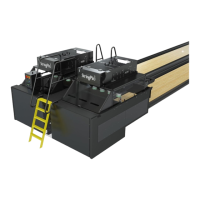
Back View
The connections at the back of the StringPin Controller handle most the higher level output voltages for
the lane pair. Refer to Figure3-5.
(1)
BALL
ACCELERATOR
POWER
(2)
PINSETTER
MOTOR
POWER
(3)
PIN LIGHT
DC
POWER OUT
(4)
EMERGENCY
STOP
(5)
PIN LIGHT
POWER
(3)
PIN LIGHT
DC
POWER OUT
(7)
PINSETTER “B”
CONNECTIONS
(6)
PINSETTER “A”
CONNECTIONS
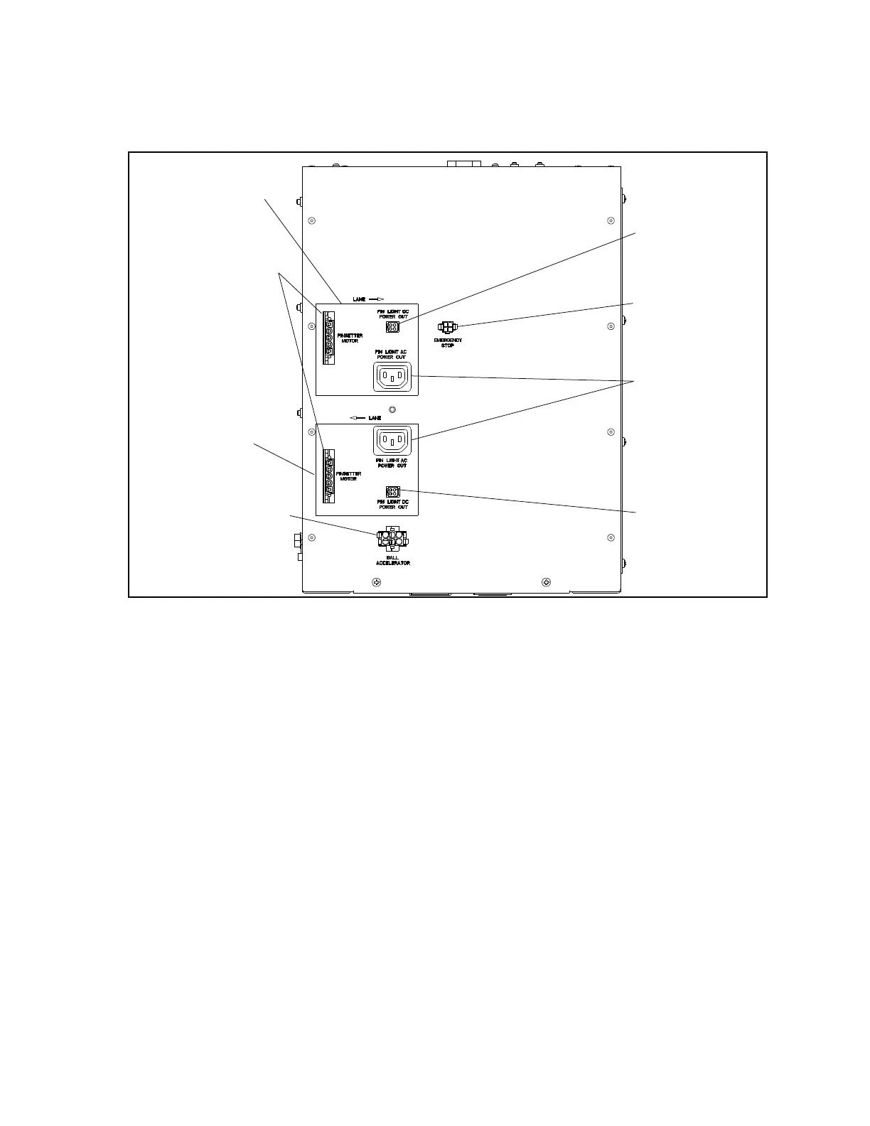
Figure3-5.StringPinControllerBox-ExternalRear
(1) Ball Accelerator Power - Connection for the 3-phase power to the ball accelerator motor.
(2) Pinsetter Motor Power - Connection for the 3-phase power to the pinsetter drive motor. Refer
to cable 55-143011-000
(3) Pin Light Power - 24VDC power for the white and black light (UV) pinlight that comes
standard with the StringPin pinsetters. Refer to cable 55-143069-xxx
(4) Emergency Stop - Connection to the external emergency stop switch.
Refer to cable 55-143013-xxx
(5) Pin Light AC Power Out- Power connection for the optional multi-color LED pinlight.
(6) Pinsetter “A” Connections - The cabling from “Pinsetter “A” connectors attach to one of the
pinsetters of the lane pair. When the controller is mounted at the rear (back) of the machines,
the connectors are used for the odd lane (left) pinsetter. When the controller is mounted at the
front of the machines the connectors are used for the even lane (right) pinsetter.
(7) Pinsetter “B” Connections - The cabling from “Pinsetter “B” connectors attach to one of the
pinsetters of the lane pair. When the controller is mounted at the rear (back) of the machines,
the connectors are used for the even lane (right) pinsetter. When the controller is mounted at
the front of the machines the connectors are used for the odd lane (left) pinsetter.