3-8 Section 3: Pinsetter Electronics
Machine Status LEDs and Start Button
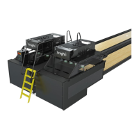
The StringPin Controller is equipped with four led lights, that can be used to indicate machine power
and the Controller reset status. Specically the LEDs monitor status of the 2 internal power contactors
which supply power to the controller’s inner circuits. There is a set of LEDs for each contactor. The red
“Power On” LED indicates that the related contactor is energized. The green “Reset” LED indicates
that the contactor is de-energized and must be re-energized by using the Start push-button.
Because the power contactors are wired in series, the each set of LEDs indicate the same information,
the status of the controller which in turn is the power status of both pinsetters. Refer to Figure3-6.
MACHINE STATUS LEDs AND
START BUTTON
(2)
MACHINE
STATUS LEDs
(2)
MACHINE
(3)
START BUTT
Figure3-6.PowerOnLights-ResetLights-StartButton
(1) MACHINE STATUS LEDS AND (2) MACHINE STATUS LEDS (3) START BUTTON
START BUTTON
Stop/Run Switches
The StringPin Controller is equipped with two Stop/Run switches, one for each pinsetter. These
switches are used to temporarily turn o the pinsetter so that the touchscreen can be used to change
the mode, clear error codes, and perform other functions for a pinsetter. . The arrow indicates which
pinsetter the switch controls. Refer to Figure3-7.
LEFT/RIGHT MACHINE ST
(2)
STOP/RUN
(2)
STOP/RUN
SWITCH
Figure3-7.Left/RightMachineStop/RunSwitch
(1) LEFT/RIGHT MACHINE (2) STOP/RUN SWITCH
STOP/RUN SWITCH