Section4:Adjustments 4-11
PIN SLOW SETTING ADJUSTMENTS
NOTE:TheSlowPincamisfactorysetandshouldnotneedadjusting.Beforeadjustingthe
SlowPincam,verifythestringtensionforeachpinisproperlyadjusted.
1. Turn the pinsetter power on. Knock down some pins and block the ball detect beam to simulate
a ball detection. When the string wagon travels to the rear of the string pinsetter, turn o the
pinsetter power. The pins will travel to the pindeck by gravity.
2. Lock out power to the pinsetter.
Warning! Pinsetter power is to remain o while performing any manual function.
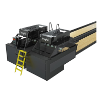
3. Manually rotate the large drive pulley in reverse until the string wagon lever roller starts to
touch the inside of the pin slow setting bracket. Refer to Figure4-11.
4. Lock the large drive pulley at this position using a tool or clamp.
5. Measure the distance the bottom of pins to the pin deck.
If using pins 1, 2, or 3 for your measurement, the distance should be 60 mm ±20 mm. If using
pins 4, 5, 6, 7, 8, 9, or 10, the distance should be 80 mm ± 20 mm.
6. If the distance is greater than 80 mm (pins 1-3) or 100 mm (pins 4-6, 7-10), adjust the pin slow
setting brackets forward. If the distance is less than 40 mm (pins 1-3) or 60 mm (pins 4-6,
7-10), adjust the pin slow setting brackets rearward.
NOTE:Thepositionofthebracketsmustbethesameonbothsidesofthemachine.