Section 3: Pinsetter Electronics 3-3
STRINGPIN PINSETTER CONTROLLER
The StringPin Controller is responsible for all functions and operations for both pinsetters on a
lane pair. It receives incoming power and makes it available to the string wagon drive motor and
ball accelerator motor and pinlights as needed. It also receives the signals from the switches on
each machine and controls the solenoids within the Pin Motion Interfaces (PMI). The following is a
description of the Controller’s components and connections.
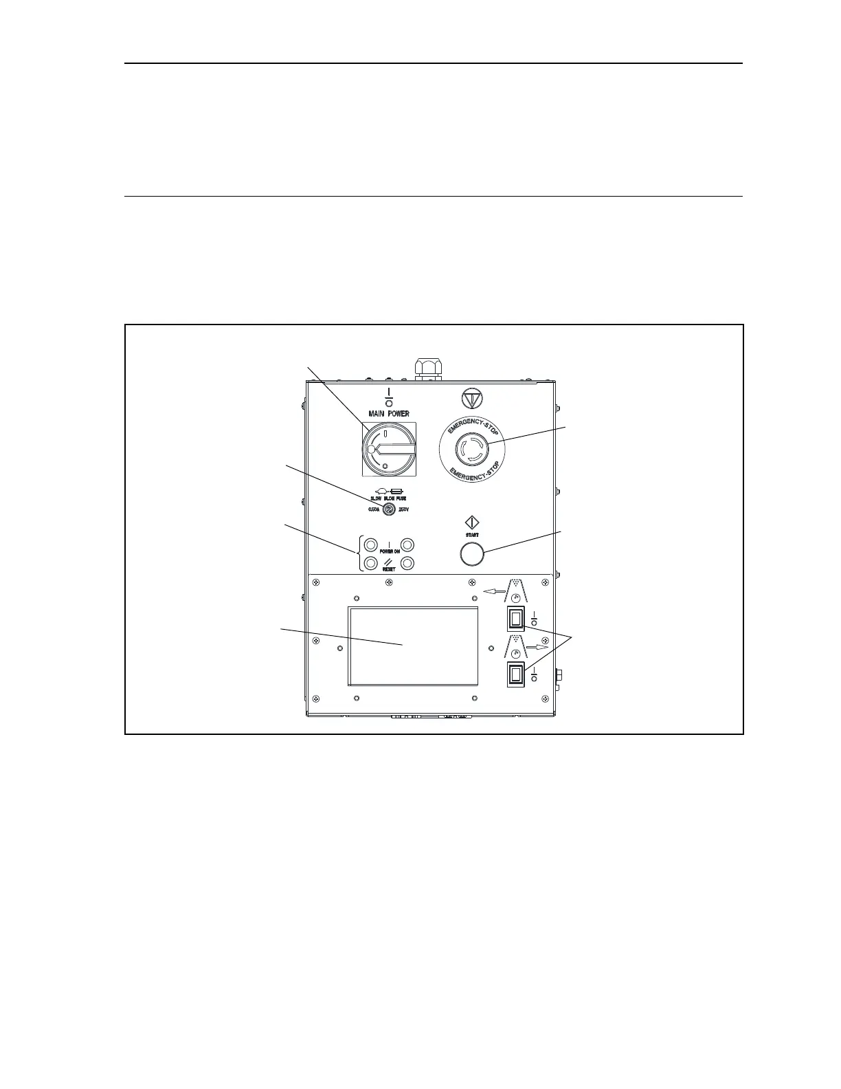
External Connections and Controls
Front View
On the front of the StringPin Controller are the components used to control and monitor the lane pair.
Controls include a main power switch, emergency o switch, stop/run switches, a start push-button,
status LEDs, and an interactive touchscreen. Refer to Figure3-3.
MAIN POWER
SWITCH/LOCK OUT
(2)
EMERGENCY ST
(E-STOP)
(5)
STATUS
LEDS
(4)
START
BUTTON
(6)
STOP/RUN
SWITCHES
(7)
LCD
TOUCHSCREEN
(3)
PULSE
CONTROLLER
FUSE
Figure3-3.StringPinControllerBox-ExternalFront