3-2 Section 3: Pinsetter Electronics
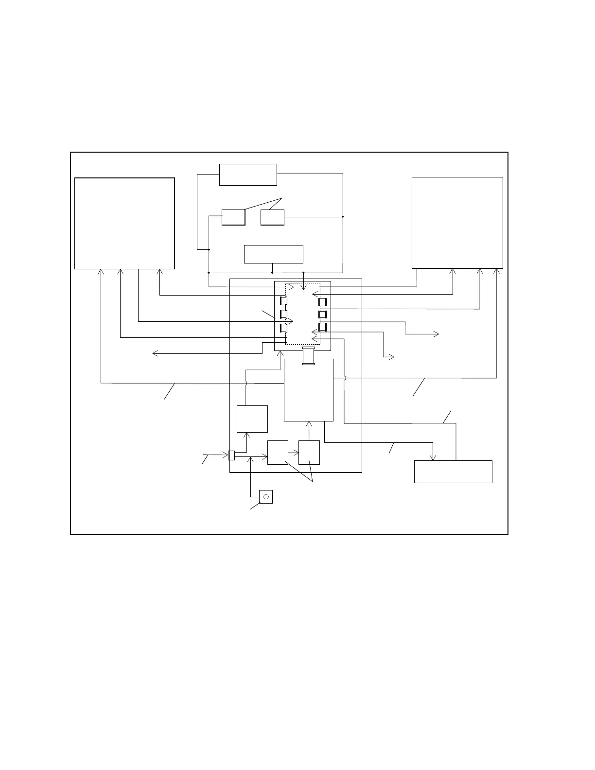
The CPU gathers switch information and sends out solenoid voltage to each pinsetter through the I/O
board. The CPU also supplies power for the D/C pinlight and the masking unit 1/2 ball lights through
the I/O board. Communication to the scorer is also handled by the CPU.
3-phase power is supplied to the High Voltage board through power contactors that are monitored
through an emergency o interlock system. The High Voltage board supplies power for the ball
accelerator, pinsetter string wagon motor, and optional A/C pinlights. Refer to Figure3-2.
(1)
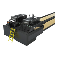
STRINGPIN
PINSETTER
“A”
(3)
TEL-E-FOUL
(4)
BALL DETECT
(7)
SOLENOIDS
(8)
SWITCHES
(17)
MOTOR /
OPTIONAL
A/C PINLIGHT
(10)
BALL ACCELERATOR
(13)
3 PHASE
POWER
(8)
SWITCHES
(7)
SOLENOIDS
(14)
BALL RACK/LIFT
(16)
EMERGENCY
(2)
STRINGPIN
PINSETTER
“B””
(11)
POWER
SUPPLY
(15)
POWER
CONTACTORS
(9)
D/C PINLIGHT
(9)
D/C
PINLIGHT
(12)
I/O
PCB
(5)
CPU
(6)
HIGH
VOLTAGE
(18)
SCORER
COMMUNICATION
(19)
MASKING
UNIT
(19)
MASKING
UNIT
(20)
POWER
(21)
OVERLOAD
(17)
MOTOR /
OPTIONAL
A/C PINLIGHT
Figure3-2.PinsetterBlockDiagram
(1) STRINGPIN PINSETTER “A” (2) STRINGPIN PINSETTER “B” (3) TEL-E-FOUL
(4) BALL DETECT (5) CPU (6) HIGH VOLTAGE
(7) SOLENOIDS (8) SWITCHES (9) D/C PINLIGHT
(10) BALL ACCELERATOR (11) POWER SUPPLY (12) I/O PCB
(13) 3-PHASE POWER (14) BALL RACK / LIFT (15) POWER CONTACTORS
(16) EMERGENCY OFF SWITCH (17) MOTOR / (18) SCORER COMMUNICATION
OPTIONAL A/C PINLIGHT
(19) MASKING UNIT (20) POWER (21) MOTOR OVERLOAD