Section 3: Pinsetter Electronics 3-5
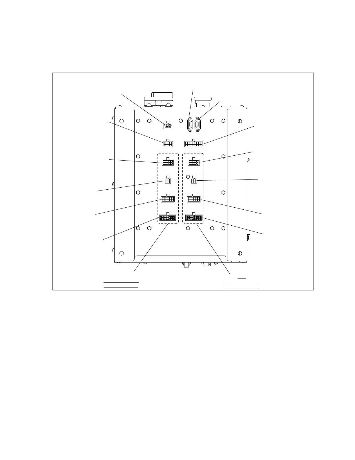
Bottom View
The connections at the bottom of the StringPin Controller handle most of the low voltage input signals
and output voltages for the lane pair as well as the communication to the scoring system. Refer to
Figure3-4.
(6)
NOT USED
(5)
BALL ACCELERATOR
MOTOR OVERLOAD
(9)
BALL RACK /
FOUL /
BALL DETECTORS
(4)
MACHINE SWITCHES /
TROUBLE LIGHT
(3)
MASKING UNIT
BALL LIGHTS
(2)
PMI
SWITCHES
(1)
PMI
SOLENOIDS
(11)
PINSETTER “B”
CONNECTIONS
(7)
JDP2 - OUT
SCORER COM-LINE
(8)
JDP1 - IN
SCORER COM-LINE
(10)
PINSETTER “A”
CONNECTIONS
(1)
PMI
SOLENOIDS
(2)
PMI
SWITCHES
(3)
MASKING UNIT
BALL LIGHTS
(4)
MACHINE SWITCHES /
TROUBLE LIGHT
Figure3-4.PulseStringPinControllerBox-ExternalBottom
(1) PMI (Pin Motion Interface) Solenoids - Connection to the solenoids located inside the PMIs.
Refer to cables 55-143009-000 and 55-143012-xxx.
(2) PMI (Pin Motion Interface) Switches - Connection to the switches located inside the PMIs.
Refer to cables 55-143009-000 and 55-143012-xxx.
(3) Masking Unit Ball Lights - Connection to the 1st/2nd ball lights on the masking unit.
Refer to cable 55-143015-xxx
(4) Machine Switches/Trouble Light - Connection to the Switch Cluster, Tangle Switch, Mechan-
ic’s Stop Switches, and the Trouble Light. Refer to cables 55-143010-000 and 55-143068-xxx
(5) Ball Accelerator Motor Overload - Connection to the overload circuit located inside the Ball
Accelerator Motor. Refer to cable 55-143014-xxx