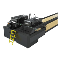
3-20 Section 3: Pinsetter Electronics
(4) Home - Located on the switch cluster, the Home magnetic switch is used to turn o the motor
when the string wagon is at home/front position of the mainframe and the pins have been set
on the pin deck if applicable. When actuated by a magnet, the display will show the switch as
“closed.”
(5) Pins Up - Located on the switch cluster, the Pins Up magnetic switch is used to turn o the
motor when the string wagon reaches the proper position at the back of the mainframe so that
the string wagon can lock on the stop dogs.
(6) Pin Solenoid - Located on the switch cluster, the Pin Solenoid magnetic switch is used to
energize the PMI (Pin Motion Interface) String Brake Solenoids at the proper time to prevent
pins from being set on the pin deck. This is normally utilized in a second ball standing pins
cycle.
(7) Reset - Located on the Ball Lift/Ball Rack that is installed near the bowler’s settee area, the
reset switch allows the pinsetter to cycle or “reset” pins. This switch will cause the pinsetter
to cycle from rst ball to second ball, then when pressed again, from second ball to rst ball
setting all 10 pins on the pin deck. When pressed, the display will show the switch as “closed.”
(8) Run/Stop - Located on the 360 Controller or on the side of the pinsetter mainframe are Run/
Stop switches. These switches are used to temporarily stop the pinsetter in the event that minor
maintenance needs to be done on the pinsetter.
(9) Tangle - Located on the mainframe of the StringPin pinsetter, the Tangle switch is used to
determine if two or more pin strings have become intertwined or tangled. If the machine cannot
detangle the pins on its own using a preset detangle sequence, the machine will turn o and
report a Tangle-01 error code.
(10) Foul - Located at the beginning of the lane, and at the end of the approach, are Foul units. One
for each lane pair. The purpose of the Foul unit is to alert the bowler and the StringPin pinsetter
that a foul as occurred, a signal will be sent from the Foul unit to the 360 Controller via a lane
cable and the controller will detect the signal and perform a foul cycle when the foul unit is
triggered.
(11) Ball Detect - Located in between a lane par, at the end of the lane and in front of the pin deck
are two Ball Detects. The purpose of the Ball Detect is to detect if a ball has entered the pin
deck area. Once the Ball Detect beam as been broken, the pinsetter will read pin fall, if any, and
cycle accordingly.
(12) Pin 1-10 - Located on the PMI (Pin Motion Interface), the Pin 1-10 magnetic switches are
utilized to detect pin fall.
(13) Exit - Selection to exit the Switch Diagnostics Screen.
Explanation of Switch State:
(14) Open - Indicates the switch is not actuated or a signal from foul or ball detector is not being
sent or received.
(15) Closed - Indicates the switch is actuated or a signal from foul or ball detector is being sent and
received.