Section4:Adjustments 4-9
2. Observe and Adjust
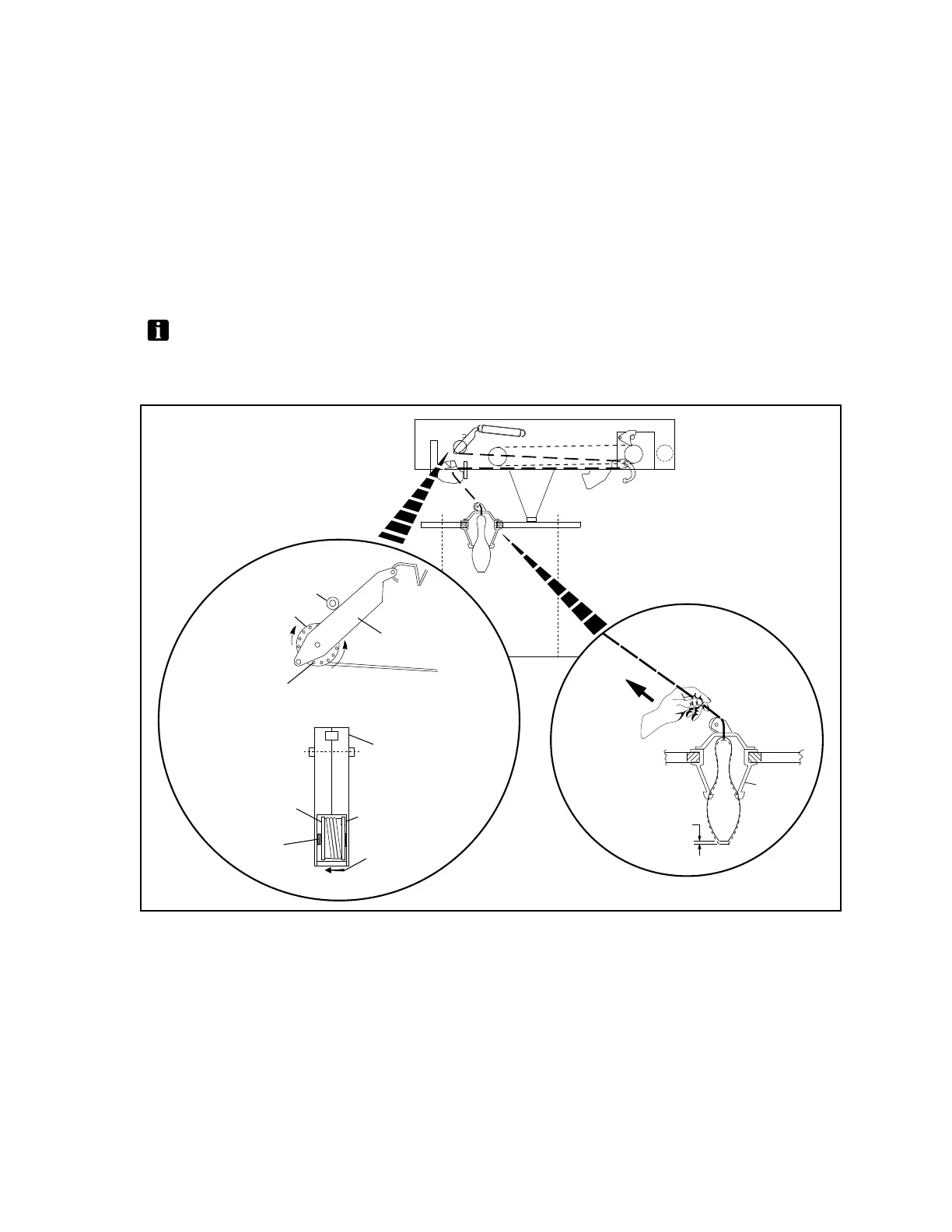
a. Check the movement of a raised pin in the pin centering cone by pulling on its string. The
travel distance of the pin should be 1-3 mm + 2 mm. Refer toFigure4-9.
b. If the tension adjustment is required for any of the pins. Refer to Figure 4-9;
Slide the string spool away from locking pins to release the spool reel.
Rotate the string reel as needed to obtain the 1-3 mm + 2 mm travel distance.
When the proper gap has been obtained, move the string reel to the right rotating it as
required to align its holes with locking pins.
NOTE:Rotatingthespooltowardsthebackofthemachinewillreducethetensionandgap.
Rotatingthespooltowardthefrontofthemachinewillincreasethetensionandgap.Referto
Figure 4-9.
(1)
CENTERING
CONE
(2)
1-3 mm
± 2 mm
(3)
LIMITER
BAR
(12)
SPOOL
LOCKING
PIN
(7)
STRING
TENSION
ADJUSTMENT
HOLES
(4)
TENSION
LEVER
(5)
STRING
SPOOL
(5)
STRING
SPOOL
(4)
TENSION
LEVER
(6)
SIDE VIEW
(8)
FRONT VIEW
(11)
SPOOL
LOCKING
SPRING
(9)
(10)
(13)
SLIDE SPOOL
TOWARD SPRING
TO UNLOCK
Figure4-9.StringTensionAdjustments
(1) CENTERING CONE (2) 1-2 MM ± 2 MM (3) LIMITER BAR
(4) TENSION LEVER (5) STRING SPOOL (6) SIDE VIEW
(7) STRING TENSION (8) FRONT VIEW (9) ROTATE SPOOL TO TIGHTEN
ADJUSTMENT HOLES
(10) ROTATE SPOOL TO LOOSEN (11) SPOOL LOCKING SPRING (12) SPOOL LOCKING PIN
(13) SLIDE SPOOL TOWARD SPRING
TO UNLOCK