99
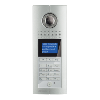
D45 VIDEO DOOR ENTRY SYSTEM
322010 - Digital entrance panel conFiguration
possible ep conFiguration moDes
MODE 1 MODE 2
Resistor conguration √ √
Keyboard conguration √ √
RS232 conguration √ √
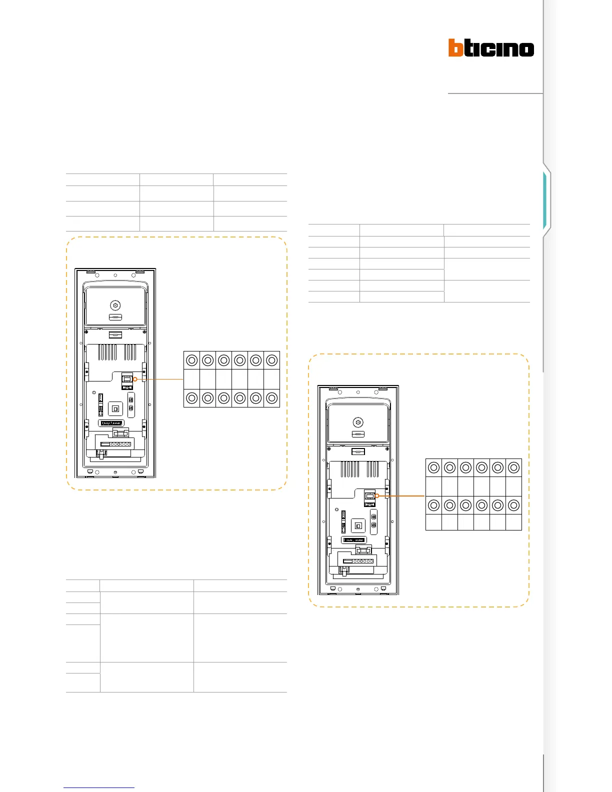
meaning oF each conFigurator socket pin
POSITION MODE 1 MODE 2
N NN Mode 2= Mode 1
N
#FF is 20(default).
No need for conguration
#FF
(
(use EP keyboard cong or 323020
download cong)
#II is 4(default).
No need for conguration
use EP keyboard cong or 323020
download cong)
NN: the number for the main EP, the number range is from
1 to 80, which means that the maximum main EP in riser is
80 (default value: 1).
#FF: typical floors per riser
#II: typical number of handsets per floor
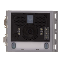
conFigurators position For ep
Example (A):
EP address is 5, each riser has 20 floors, and each floor has 4
handset: system configuration mode 1 is used.
The Switchboard directly connected to the main EP is no. 2,
main EP configuration should be as follows:
POSITION VALUE FOR CONFIGURATOR REMARKS
N 0 0
N 5
#F
#FF is 20(default).
No need for conguration
#F
#I #II is 4(default).
No need for conguration
#I
C 2This position can use the EP keyboard or the configuration tool for the
configuration.
Note:the other configuration position C is for setting the Switchboard address
number that will communicate with the EP directly. The configuration position C
can only be configured using the EP keyboard or the configuration tool software. (C
default value: 0; this means that the Switchboard that will communicate with the
EP is No.0)
a
N N #F #F #I #I
0 5
N N #F #F #I #I
EP configuration examples

 Loading...