103
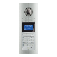
D45 VIDEO DOOR ENTRY SYSTEM
323003 - riser shunt conFiguration
possible riser shunt conFiguration proceDure
MODE 1 MODE 2
Resistance conguration √ √
Keyboard conguration √ √
Use RS232 conguration √ √
meaning oF each conFigurator socket pin
POSITION MODE 1 MODE 2
CF1
NNNN NNNN
CF2
CF3
CF4
CF5
#FF is 20(default).
No need for conguration
#FF
(#II setup using same value for all system
riser shunts).
CF6
CF7
#II is 4(default).
No need for conguration
#II
(#II setup using same value for all system
riser shunts).
CF8
C C C
M M M
NNNN: number of riser shunts
#FF: typical floor number for riser
#II: typical number of handsets for each floor
#Min handset: the lowest handset address managed by this
riser shunt.
#Max handset: the highest handset address managed by
this riser shunt.
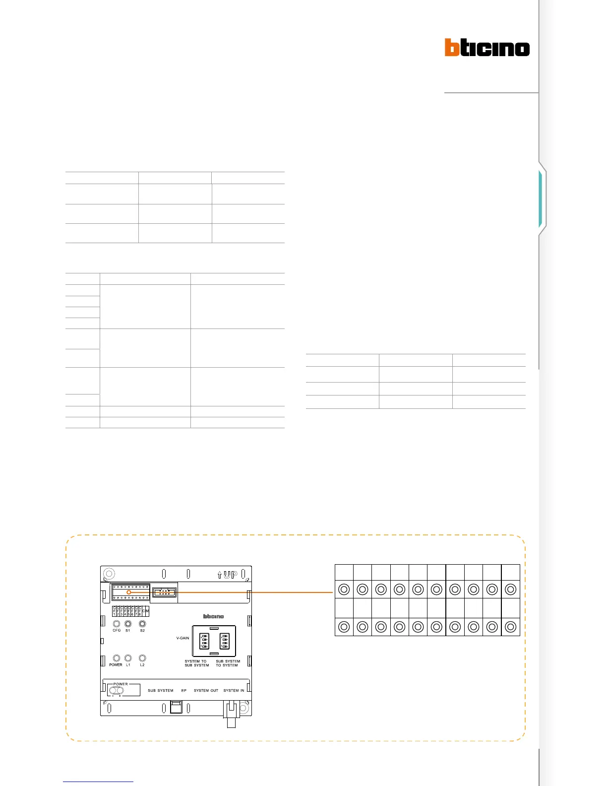
riser shunt conFiguration position
CF1 CF2 CF3 CF4 CF5 CF6 CF7 CF8 C M
N N N N #F #F #I #I C M
ON
SD
1
2
3
4
ON
SD
1
2
3
4
Accessory configuration examples
C: the Switchboard number that is the first priority for this
riser. If the number of the Switchboard is more than 9 (from
10 to 15), this parameter can only be set using the riser shunt
keyboard or the system configuration software tool.
M: System configuration mode. If the selected configuration
mode is Mode 1 or mode 2, this parameter is 0. If this
configurator is set using number 2, it means that this riser
shunt is only used inside the riser to extend the maximum
number of handsets (from 400 to 800 ).
If 323011 is present in the system or switchboard is install in
the riser than an additional configuration is needed for riser
shunt as below listed :
Configuration can only be set by SF2 software or by
keyboard.
CONFIGURATION BIT DEFINITION REMARK
CF11 CF12 First EP number in this riser From 1 to 80
CF13 CF14 Riser EP quantity of riser
CF15 CF16 Riser switchboard number From 1 to 15

 Loading...