Example (A):
The number of riser shunts is 5, each riser has 20 floors,
and each floor has 4 handsets. The Switchboard that can
be called directly by this riser is no. 2. System configuration
mode 1 is used. The riser shunt configuration should be as
follows:
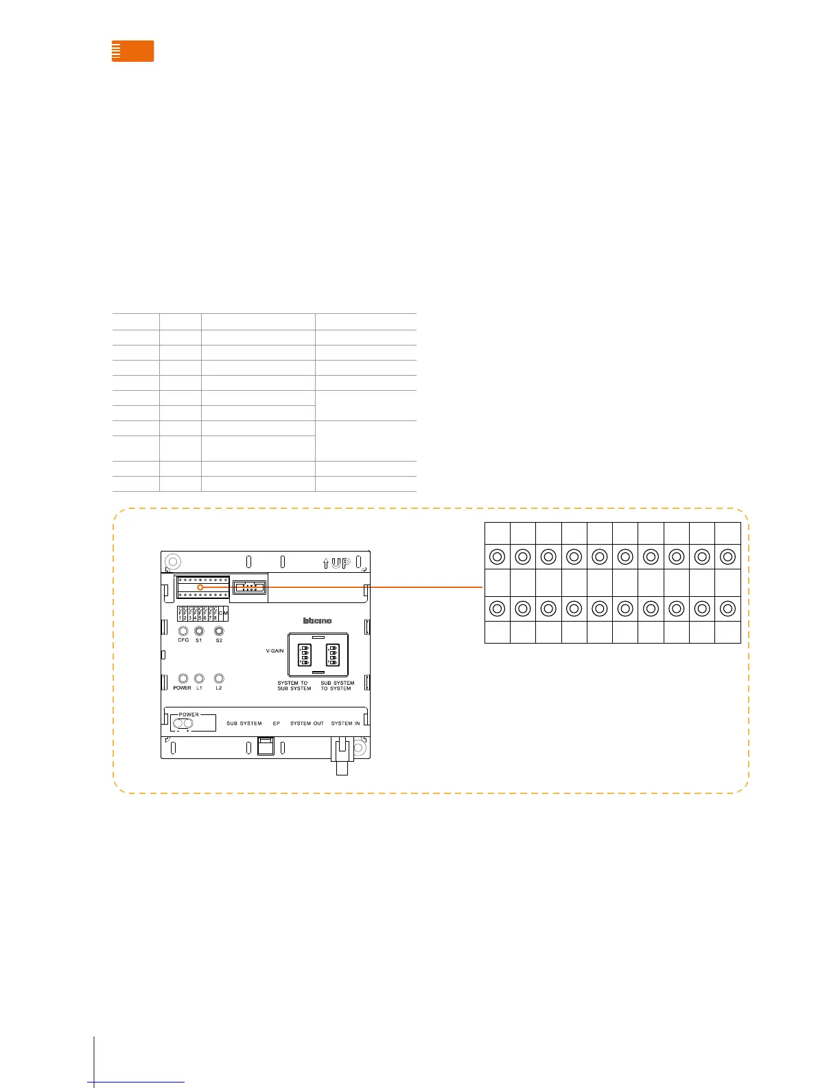
POSITION MODE 1 VALUE FOR CONFIGURATOR REMARKS
CF1 N 0 0 no cong needed
CF2 N 0 0 no cong needed
CF3 N 0 0 no cong needed
CF4 N 5
CF5 #F
#FF is 20(default).
No need for conguration
CF6 #F
CF7 #I #II is 4(default).
No need for conguration
CF8 #I
C C 2
M M 0 0 no cong needed
a
CF1 CF2 CF3 CF4 CF5 CF6 CF7 CF8 C M
N N N N #F #F #I #I C M
0 0 0 5 2 0
ON
SD
1
2
3
4
ON
SD
1
2
3
4
323003 - riser shunt conFiguration
Accessory configuration examples

 Loading...