101
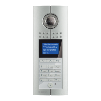
D45 VIDEO DOOR ENTRY SYSTEM
321010 - possible hanDset conFiguration
proceDure
MODE 1 MODE 2
Resistor conguration
(only for Colour)
√ √
Keyboard conguration √ √
RS232 conguration × ×
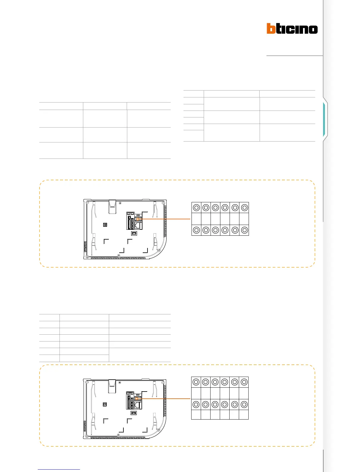
meaning oF each conFigurator socket pin
POSITION MODE 1 MODE 2
F FF FF
F
I II II
I
#I Default for #II is 04,
need not connect the congurator
II
(#II setup using same value for all system
handsets).
#I
FF: Handset floor number
II: handset household number
#II: typical number of handsets per floor
Example (A):
The number of handsets is 1204, each floor has 4 handsets,
the system configuration mode is Mode 1, the handset
configuration should be as follows:
POSITION CONFIGURATION VALUE REMARKS
F 1
F 2
I 0 It is ok not to insert congurator 0
I 4
#I Because the default value of #II is 4, no
congurator is needed
#I
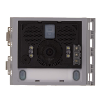
conFigurators position For hanDsets
a
F F I I #I #I
F F I I #I #I
1 2 0 4
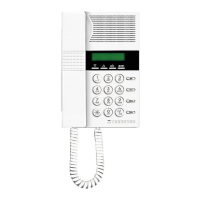
Handset configuration examples

 Loading...