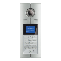
346858 - D45 to 2 wire interFace
346858 can be configured in two ways: 1) simple
configuration (Mode 1); 2) flexible configuration (Mode 2)
CF2 CF4 CF6 CF8
F I #I MC
CF1 CF3 CF5 CF7
Remarks. FFII= the number of the handset (FF refers to the
first two places of the IP number and II refers to the last two
places, namely the room number at the floor).
CONFIGURATION
PLACE
SIMPLE CONFIGURATION
MODE 1
FLEXIBLE CONFIGURATION
MODE 2
CF1
FF= the oor number relevant to
the HANDSET (01≤FF≤20)
FF= the oor number relevant to the IP
(01≤FF≤99)
CF2
CF3
II=the room number relevant to
the IP oor (01≤II≤04)
II=the room number relevant to the IP
oor (01≤II≤#II)
CF4
CF5
#II (Mode 1, default 04, no need
to set)
#II=household number of the unit
(01≤#II≤99)
CF6
CF7 MC (no need to set, relying on
the setting of the Riser shunt)
MC (no need to set, relying on the setting
of the Riser shunt)
Note: MC refers to the address of the Switchboard, with no need to set on 346858,
relying on the C-place setting on the Riser shunt.
example
1. If the unit building relevant to 346858 has 18 floors, 4
households on each floor, then D45 system can use
Mode 1 for the system configuration. If the 346858 floor
is 17/F and the second household, then its configuration
can be as follows:
CONFIGURATION
PLACE
SIMPLE CONFIGURATION
MODE 1
CF1
FF=17
CF2
CF3
II=02
CF4
CF5
Default 04, no need to set
CF6
CF7 No need to set, relying on the setting of the Riser shunt
2. If the unit building relevant to 346858 has 28 floors, 3
households on each floor, then D45 system can use Mode
2 for the system configuration. And the 346858 floor is
10/F and the second household, then its configuration
can be as follows:
CONFIGURATION
PLACE
SIMPLE CONFIGURATION
MODE 2
CF1
FF=10
CF2
CF3
II=01
CF4
CF5
#II=03
CF6
CF7 No need to set, relying on the setting of the Riser shunt
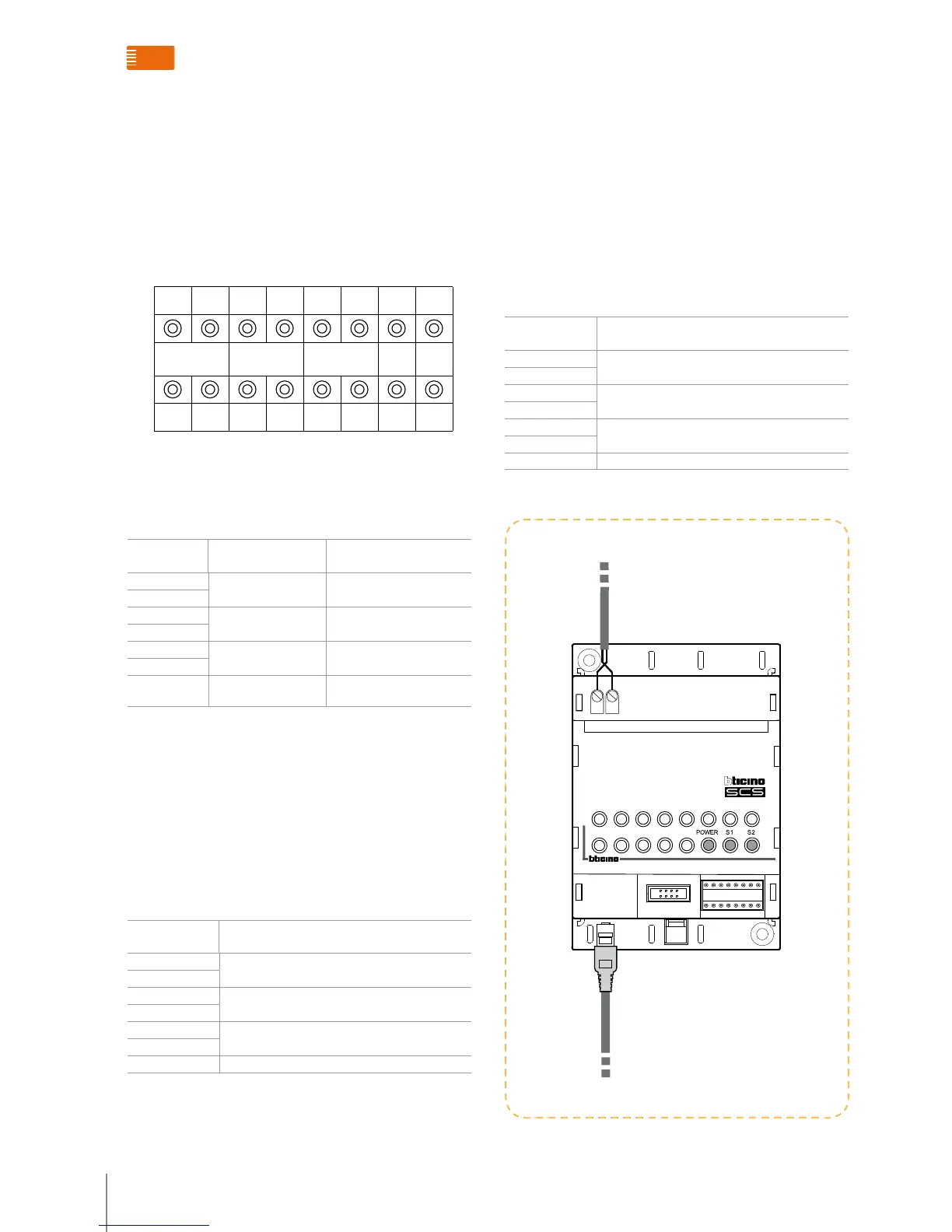
Wiring method for 346858
Remarks: 346858 will automatically get its power from
BT’s 2-wire connection end of INT.
BTicino 2 WIRE SYSTEM
FLOOR SHUNT (HANDSET INTERFACE)
346850_front
346850
INT
EXT

 Loading...