21
D45 VIDEO DOOR ENTRY SYSTEM
Drawings as above, set at the back of the handset according
to the marks. Default is master handset. After setting,
reconnect the power to activate the new settings.
Installing Small EPs
If a Small EP is required, connect the Small EP to the “Small
EP connector” on the master handset. You can enable the
monitoring Small EP function during installation setup.
Install Small EPs door lock releases
If an electric door lock release is required for the Small EP,
a door lock accessory is required for the door lock release
function.
External SOS switch
The external SOS switch is installed at the back of the handset
“SOS alarm connector” and can be set as always open (NO
type) or always closed (NC type) using the keyboard. The
default status is always open (NO type).
Alarm sensors connections
8 alarm defence areas can be defined for each IU. Infrared
theft sensors,door sensors,smoke and gas sensors can
be connected directly to the IU. Check that the cable
connections between the IU and the sensors are correct
and avoid cable cutting. When connecting sensors, a 10
K parallel resistor + a 10 K resistor in series are required.
Resistors should be placed close to the sensor port in order
to ensure that an alarm can be sent when the handset is
forcefully removed.
Note : IU can afford 12 Vdc sensors type and total sensors current should not exceed a
maximum of 300 mA. If maximum current is more than 300 mA, than an additional
power supply must be used. Maximum cable distance between sensors and IU is ≤ 50 m,
suggested to use 0.5 mm
2
section cable.
Anti-removal installation for sensors
The handset alarm has an anti-removal function. The
handset has an external sensor connector. When the
Alarm sensor is removed, the handset can send an anti-
removal alarm message to the Switchboard. The connector
requires that the alarm sensor output is NC after the alarm
sensor is remove. After installation is completed and the
burglar alarm is enabled, the handset will automatically
check the anti-removal signal of the sensor. If the sensor is
removed, the handset will send an anti-removal message
to the Switchboard.
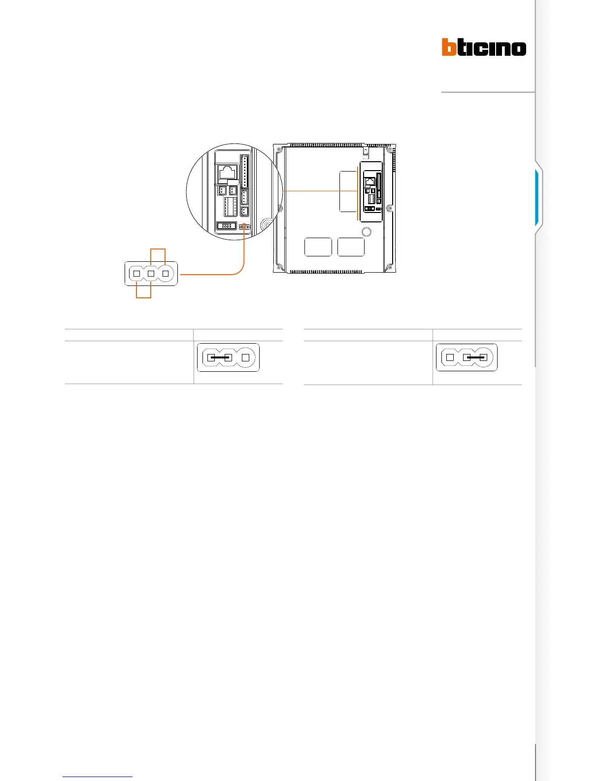
MASTER AND SLAVE SETTINGS MASTER
Set as the master handset
Or not jump
master anD slave settings
Slave
Master
MASTER AND SLAVE SETTINGS SLAVE
Set as the slave handset

 Loading...