43
D45 VIDEO DOOR ENTRY SYSTEM
POWE R
+
-
1 2 3 4
1 2 3 4
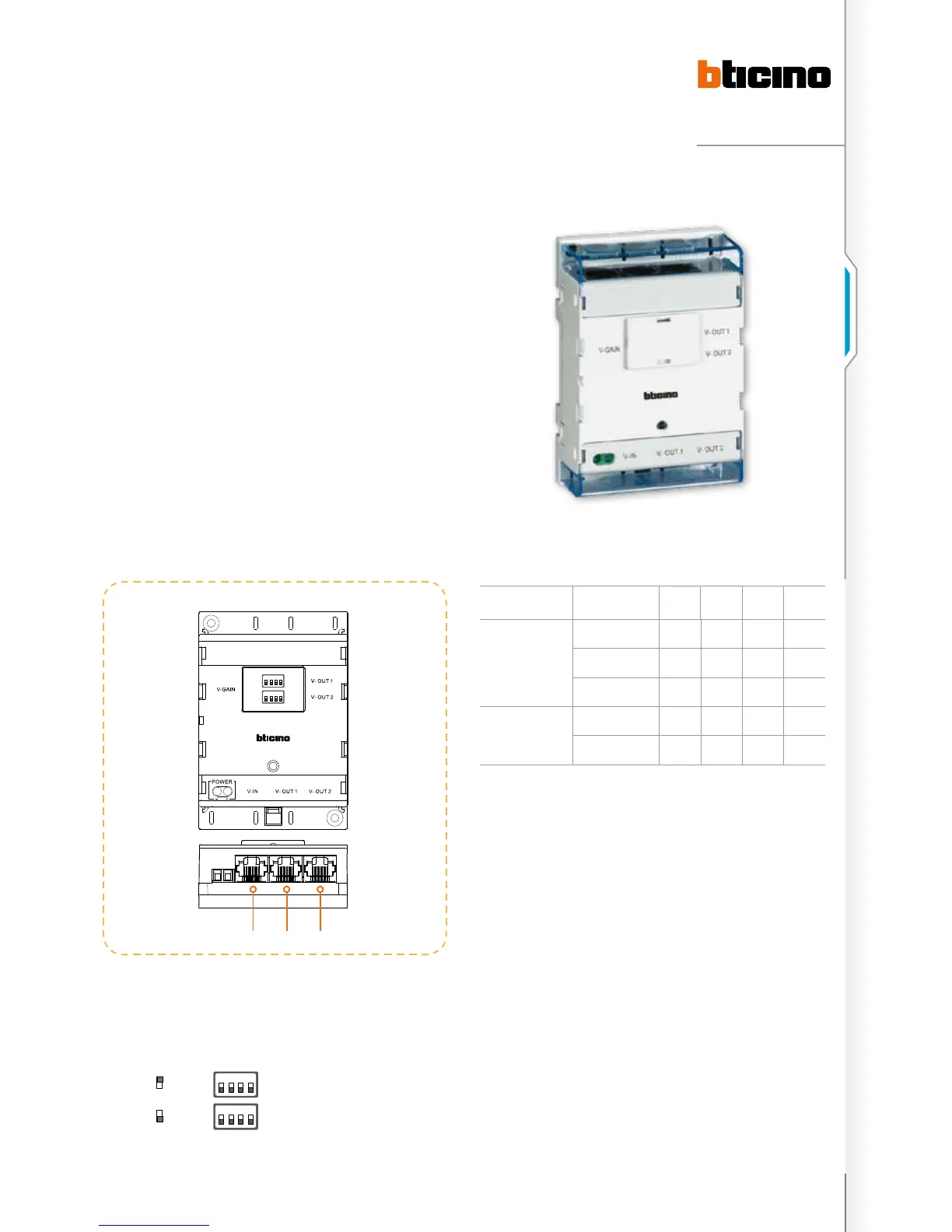
legenD
1. BUS input connector.
2. Branch 1 output connector.
3. Branch 2 output connector.
1 2 3 4
1 2 3 4
on
oFF
Branch 1 V-GAIN switch
Branch 2 V-GAIN switch
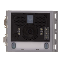
2 Branches video splitter
323007 - 2 branches viDeo splitter
The device has one input and two outputs. It splits the
BUS signal into two channels: the video signal can only be
transferred from input to output. The video Splitter has
4 gears for video compensation functions. It can provide
compensation to two channels separately and make the
video signal output from EP adapt to different transfer
distances by setting different gears. It mainly use in riser
systems to divide the riser BUS into many channels to adapt
to the wiring in many low electricity wells. One building that
is particularly high will use 323007 to adjust video gains by
splitting in two channels. One channel will be used for lower
floors, the other is for higher floors. 323007 also can be used
for physically connecting the Switchboard and extend the
Switchboard interface. (in this case, if the Switchboard is
fitted with a camera, the video signal cannot be transmitted
to the handset).
DIP switch setting instruction
Distance 1 2 3 4
COLOUR SIGNAL
0 – 300 m OFF OFF OFF OFF
300 – 700 m ON OFF OFF OFF
700 – 1000 m ON ON OFF OFF
B/W SIGNAL
1000 –1500 m ON ON ON OFF
1500 – 2000 m ON ON ON ON
The instruction data in above table may be different
during actual installation.
1 2 3

 Loading...