5
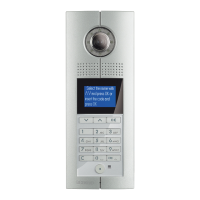
D45 VIDEO DOOR ENTRY SYSTEM
legenD
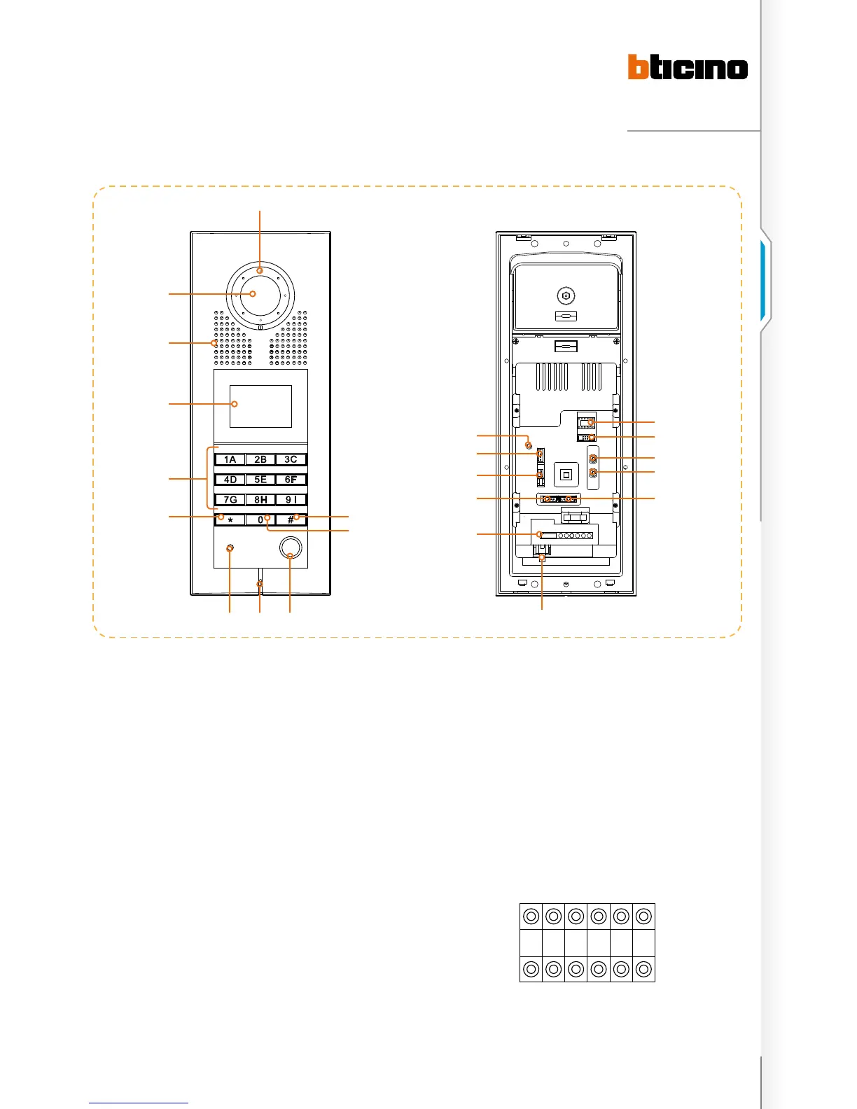
1. Compensation Lamp
2. Confirm menu setting or other operation
3. Number keyboard: call the handset and function setting
4. Management centre pushbutton: call the Switchboard
5. Microphone
6. Photosensitive lamp
7. Return or quit menu setting
8. Alphanumerical pushbuttons
9. Access control lens (Optional)
10. Loudspeaker
11. Camera: to view the image
12. NN #FF #II: configurator
13. ISP: entrance panel software upgrade connector
14. SPK: ADJUST loudspeaker volume
15. MIC: ADJUST microphone volume
16. VIDEO-IN/GND/NC/+12V/LED-: connect entrance panel
camera and compensation Lamp
17. SYSTEM BUS uses CAT5 cable to connect to system
18. 7P connector
+12 V/GND: supply power to A/C module
DOOR LOCK RELEASE: door lock release signal output by
A/C module
GND/DAS: electronic lock status signal connector
LOCK-/LOCK+: connect electronic lock.
19. SPK-OUT/GND/GND/SPK-OUT: connect entrance panel
loudspeaker
20. V-GAIN: video gain setting
21. ANT: connector for A/C module antenna
22. RESET: for password reset
entrance panel parameter conFiguration
Entrance panel parameters setting by configurator. After
changing the parameters the Configurator must be switched
off and on again.
NN: Entrance panel address
# FF: Floor quantity in a riser
# II: Maximum internal unit (apartments) for each floor in
the same riser
N N #F #F #I #I
322010
1
11
10
9
8
7 2
3
6 45
21
19
18
17
16
15
14
13
12
20
22

 Loading...