37
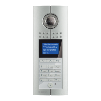
D45 VIDEO DOOR ENTRY SYSTEM
Video gain setting instruction (switch up ON, switch down
OFF)
Note: users can switch the DIP switch to adjust according the actual video conditions.
B/W SIGNAL
Distance 1 2
1000-1500 m ON OFF
1500 - 2000 m ON ON
Note: The instruction data in the above table are suggestions for the B/W signal.
They may differ during the actual operation. Irrespective of whether it’s a colour (less
than 1000m) or B/W signal, please take into account the actual image when setting
the data.
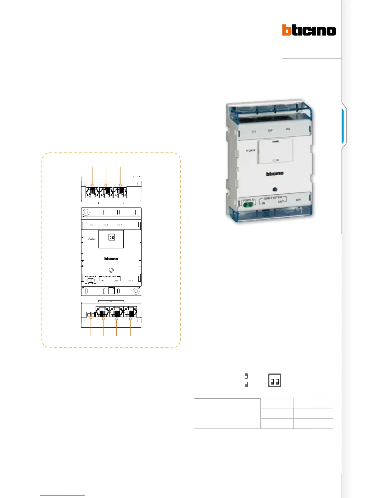
Floor shunt
323002 - Floor shunt
A floor shunt should be installed between floors. Using a
signal cable, each apartment handset is connected to the
BUS through item 323002. One 323002 can be connected
to 4 handsets. The device converts the BUS video signals to
transfer mode and then distributes them to the connected
handsets.
1 2
POWE R
+
-
7 6
5
4
321
1 2
on
oFF
legenD
1. Connect four handsets separately;
2. Connect four handsets separately;
3. Connect four handsets separately;
4. Connect four handsets separately;
5. Riser system BUS output connector to connect next
323002 SUB SYSTEM IN connector;
6. Riser system BUS input connector to connect last 323002
SUB SYSTEM OUT connector or 323003 SUB SYSTEM
connector;
7. Additional Power supply connector 30 Vdc.
Note: (1 – 6) these six terminals are RJ45 connectors, use a CAT5 cable.

 Loading...