323005 - power supply
323010 - auxiliary power supply
When the impedance switch is ON, 323005 is set as system
power supply: it supplies power to the data communication
cable and input audio impedance.
When impedance switch is OFF, 323005 is set as additional power
supply: it does not supply power to the data communication
cable and cuts audio impedance.
323005 The power supply device configuration is to set
power supply address, the address range or floor range
powered by the device, power supply type (system supply,
additional supply), alarm current that power supply offers to
each handset, enable or disable smart power supply and PW
management, and select system configuration mode. Only
if the configuration is correct can the system work correctly.
There are 3 configuration methods: resistor configurator,
pushbutton setup, and by SF2 software. The resistor
configurator has the highest priority. If the resistor
configurator method is used on 323005, then the other
configuration method will be ineffective.
Note: if the resistor configurator method is used, this will be validated after pressing
and holding down the S1 and S2 pushbuttons at the same time, or after the power
supply is restarted.
1. Configuration using the resistor configurator. There are
3 configuration methods using resistor configurators:
mode 1, mode 2, and mode 3. The user can choose one
of them according to the complexity of the system. The
14 th bit is used to mark the mode used. For the details
please see the system configuration chapter.
2. Pushbutton method ( only effective when the resistor
configuration method is not used)
1. Enter configuration status: in standby press input key S2
and hold for 2 s. The CFG light will be always on. Enter
the configuration setup status. (If there is a resistor
configurator installed or if the pushbutton configuration
has been performed incorrectly, the device cannot enter
configuration setup status).
2. Enter the configurator number (i.e. select one
configurator): press S2 to count. Each pressure will
increase the number by one (no press= 1st one) and the
CFG light will flash once.
3. Confirm the configurator number: press S1 then CFG
light flash quickly twice. Then it will come on steady.
4. Enter the configuration parameter: press S2, the default
parameter is 0. Increase by 1 with each pressure. The
CFG light will flash quickly twice . The highest number
possible is 9.
5. Confirm the configuration parameter: press S1, the CFG light
will flash quickly twice and then flash slowly twice. Then the
configuration procedure for this step is now completed.
6. Set the next parameters: if necessary, set the other
configuration parameters, press S2. The CFG light will
flash quickly 3 times. Then proceed according to (2).
7. If the operation is successful, the CFG light will flash
slowly once, and the entered configuration parameters
will be validated. If the configuration is not successful
(for example, one configuration exceeds the acceptable
value, e.g. M>1), the CFG light will be off, and the old
configuration will be still effective. If the configuration
value has logical errors (for example, NNN>256 or #Min
IU>#Max IU), the CFG light will keep flashing slowly to
indicate the error and pushbutton operation will be
disabled. In this case it will be necessary to connect
a non-zero (1- 9) configurator to the right position
and reconnect the power to clear the pushbutton
configuration. Then remove the configurators, reconnect
the power and repeat the above configuration steps.
If no pushbutton is pressed for 10 s during the operation,
the device will automatically exit configuration mode and
the CFG light will go off.
Configuration enquiry:
n Enter conguration enquiry status: in standby press input
key S1 and hold for 2 s. The CFG light will come on and the
device will switch to conguration enquiry status;
n Enter the conguration number (i.e. select one
congurator): press S2 to count. Each pressure will
increase the number by one (no press= 1st one) and
the CFG light will ash once.
n Conrm the conguration parameter: press S1, the
CFG light will ash quickly a number of times. This
number of times depends on the parameters being
read (for example, if the parameter read is 0, there is
no ashing, for one it will ash once, for two it will ash
twice). Other operations may be deducted by analogy.
n Exit conguration enquiry status: The CFG light will be
o. If no key is pressed for 10 s during the operation
the device will automatically switch to standby. The
CFG light will be o.
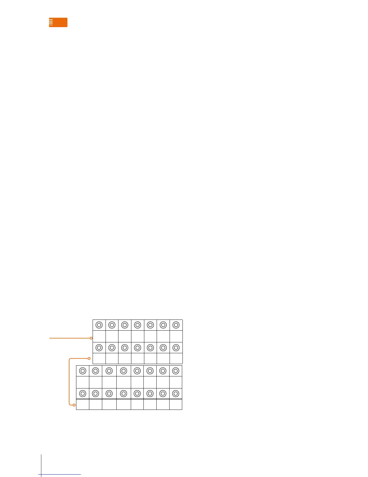
N N N CF4 CF5 CF6 CF7
1 2 3 4 5 6 7
CF8 CF9 CF10 CF11 TYP ASR M LE
8 9 10 11 12 13 14 15
Order number of configuration
0-9
Range of resistor number: 0-9
System accessories functions overview

 Loading...