35
D45 VIDEO DOOR ENTRY SYSTEM
System accessories overview
Riser shunt
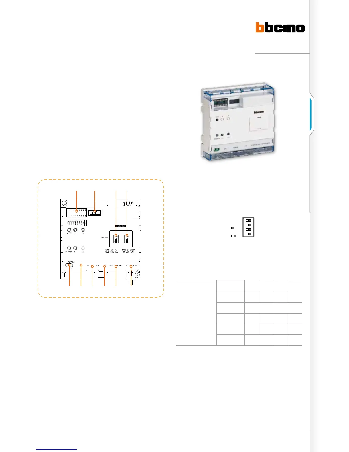
323003 - riser shunt
The riser shunt is used to connect the riser BUS and system
BUS in order to separate BUS, transfer signal and switch
between video and audio channels. The device has five RJ45
connectors, which are for riser BUS input/ output, system
BUS input/ output. The last RJ45 and two other connectors
are designed to connect the riser system to the main power
supply. The device also has 2 4-gear video gain DIP switches
for video channel from the EP to the system BUS, and video
channel from the system BUS to the HANDSET. The video
transfer distance can be increased by adjusting the gain. By
installing several items 323003 in cascade, the riser systems
can be connected as a network and managed as districts.
The following table indicates the video amplifying gains.
During the installation, the parameters need to be adjusted
according to image requirements.
DIP switch setting instruction
Distance 1 2 3 4
COLOUR VIDEO
SIGNAL
0 – 300 m OFF OFF OFF OFF
300 – 700 m ON OFF OFF OFF
700 – 1000 m ON ON OFF OFF
B/W VIDEO SIGNAL
1000 –1500 m ON ON ON OFF
1500 – 2000 m ON ON ON ON
system conFiguration instructions
The system configuration for the Riser Shunt consists in
assigning a number to item 323003, setting the address
range managed by item 323003, and selecting the system
configuration mode. Only if the configuration is correct can
the system work correctly. There are 3 configuration methods.
The configurator alternative enjoys the highest priority. If the
physical configurator is used on the Riser shunt, then the
other configuration methods will be ineffective.
Note: if use physical configurator method is used, the power of item 323003 should
disconnected after the configurator has been installed, and then reconnected to
activate the configuration.
ON
SD
1
2
3
4
ON
SD
1
2
3
4
1 2 3 4
987 10
5 6
legenD
1. Riser system power supply input connector
2. Riser system power supply input connector
3. Input connector for riser system: SUB SYSTEM IN
interface for 323002
4. Entrance panel: riser entrance panel output connector
5. Output connector for SYSTEM OUT BUS: connect the
SYSTEM IN interface of next 323003 or 323001 related
interface
6. System BUS connector for SYSTEM IN: connect last
323003 SYSTEM OUT interface or leave empty
7. System configurator connector: insert resistor
8. Configuration connector for updating the software and
connect the PC in series
9. Adjust switch of video channel gain from the system BUS
to the riser handset
10. Adjust switch of video channel gain from the riser
entrance panel to the system BUS
ON SD
1
2
3
4
on
oFF
Note: (2 – 6) these five terminals are Rj45 connectors, use a CAT5 cable.
Indication lights
- CFG: Configuration guide
- POWER: Power supply
- L1 L2: Intercom status
- S1: Confirmation
- S2: Input

 Loading...