117
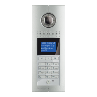
D45 VIDEO DOOR ENTRY SYSTEM
323005 - power supply conFiguration
choosing the system power solution
n Solution 1: PWS 323005 will be chosen as system power
supply inside the riser while auxiliary PWS (323010) will
be chosen for all the auxiliary power supply.
n Solution 2: PWS 323005 will be chosen for both system
power supply inside the riser and auxiliary power supply.
Note: when the system includes Small EP, solution 2 will be helpful to avoid
possible damage to the power supply in the system. When the system has
handsets connected to Small EP, sometimes if several Small EP call handsets at
the same time, a power supply overload may occur. Under this situation there is
a risk of damage to the power supply.
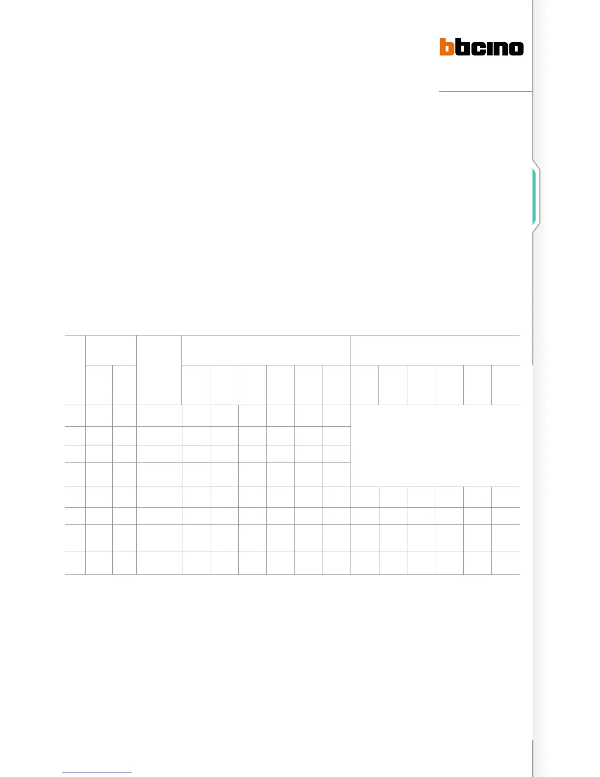
Suggested power supply solution and related configuration:
NO. SYSTEM PWS
SOLUTION
CONFIGURATION WHEN PWS IS SYSTEM POWER SUPPLY
IMPEDANCE SWITCH OF PWS MUST BE ON
CONFIGURATION OF PWS AND AUXILIARY PWS WHEN PWS
IS AUXILIARY POWER SUPPLY IMPEDANCE SWITCH OF
POWER SUPPLY MUST BE OFF
ALARM SMALL
EP
CF1
~
CF3
NNN
CF4
~
CF11
CF12
TYPE
CF13
ASR
CF14
M
CF15
LE
CF1
~
CF3
NNN
CF4
~
CF11
CF12
TYPE
CF13
ASR
CF14
M
CF15
LE
1 No No 1 X X X X X X
Here use Auxiliary Power supply, conguration is not necessary.
2 No No 1 X X X X X X
3 Yes No 1 X X X X X X
4 Yes No 1 NNN X 1 0.2–9 1 X
5 No Yes 2 NNN √ 1 1 0/1 X X √ 2 1 0/1 X
6 No Yes 2 NNN √ 1 1 0/1 X X √ 2 1 0/1 X
7 Yes Yes 2 NNN √ 1 0.2~9 0/1 X X √ 2 0.2–9 0/1 X
8 Yes Yes 2 NNN √ 1 0.2~9 0/1 X X √ 2 0.2–9 0/1 X
Note:
X: It means no configurator is needed and the configuration position is 0; others need a configurator with corresponding value.√: It means configuration is needed. For the
configuration procedure refer to the system configuration chapter.

 Loading...