323018 - ep/switchboarD shunt
Introduction to the configuration procedures
1. Resistor configurator procedure. Insert the resistor
configurator of appropriate value into the EP/
Switchboard shunt configurator to perform EP/
Switchboard shunt configuration. After connection
the resistor configurator, press both S1 and S2 for two
seconds at the same time and then release so that the
EP/Switchboard shunt can be restarted (or repowered)
for the new configuration to take effect. Note: The use of
the resistor configurator for the configuration will clear
the value configured with the pushbuttons.
2. Pushbutton configuration. Set the values of each
configuration place using the pushbuttons and configure
the EP/Switchboard shunt. You can also read the values
of each configuration place using the pushbuttons.
Note: When the resistor configurator is connected this
method will be invalid.
3. Computer serial port configuration. Use TK1 to
connect the PC and EP/Switchboard shunt, and then
enter the configuration parameters as per the manual
tool configuration operation and download it to EP/
Switchboard shunt.
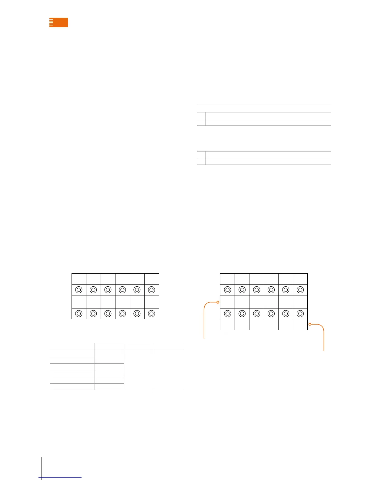
Introduction to the configuration place
CF1 CF2 CF3 CF4 CF5 CF6
MC
min
MC
min
MC
max
MC
mac
DEV DIR
Meaning of the configuration place
CONFIGURATION PLACE MODE 1 MODE 2 MODE 3
CF1
Min*
Same as Mode 1 Same as Mode 1
CF2
CF3
Max**
CF4
CF5 DEV
CF6 DIR
Nota
*Min: The minimum number connected to the Backbone/main EP or the
Switchboard at main EP/Switchboard interface.
**Max: The maximum number connected to the Backbone/main EP or the
Switchboard at main EP/Switchboard interface.
DEV: Options of main EP/Switchboard types
DEV
0 Switchboard
1 Backbone/main EP
DIR: Options of main EP/Switchboard wiring directions
DIR
0 The Switchboard is connected to the B1 interface and backbone/main EP to the B2 interface
1 The backbone/main EP is connected to B1 and the Switchboard to B2
The DIR configuration for the device wiring direction must
satisfy the following rules or irregular system operation will
occur:
1. The riser shunt must be connected to B1 of all interfaces
in the relevant zone.
2. The wiring direction of the Switchboard and the main
EP can be set through the DIR configuration place, but
all the interface wiring directions must be identically
configured in the project.
3. Pushbutton-configuration operation (it will not be valid
if the resistor is inserted in the configurator).
CF1 CF2 CF3 CF4 CF5 CF6
MC
min
MC
min
MC
max
MC
mac
DEV DIR
1 2 3 4 5 6
Value of the configuration place (from 0-9)
Code of the configuration place (1 to 6)
System accessories functions overview

 Loading...