41
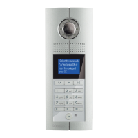
D45 VIDEO DOOR ENTRY SYSTEM
PO W E R S 1
S 2
C F G #
*
R I S E R
E P
P S
S Y S T E M IN S Y S T E M O U T
IN
P W
+
-
I U 4 O U T
S U B S Y S TE M
I U 1 I U 2 I U 3
V -G AI N
VC C - O UTGN D
BA T T
-B AT T +
UT 1
O U T 2
O U T 3
IN
P W
+
-
I U 4 O U T
S U B S Y S TE M
I U 1 I U 2 I U 3
V -G AI N
VC C - O UTGN D
BA T T
-B AT T +
UT 1
O U T 2
O U T 3
VC C - O UTGN D
BA T T
-B AT T +
UT 1
O U T 2
O U T 3
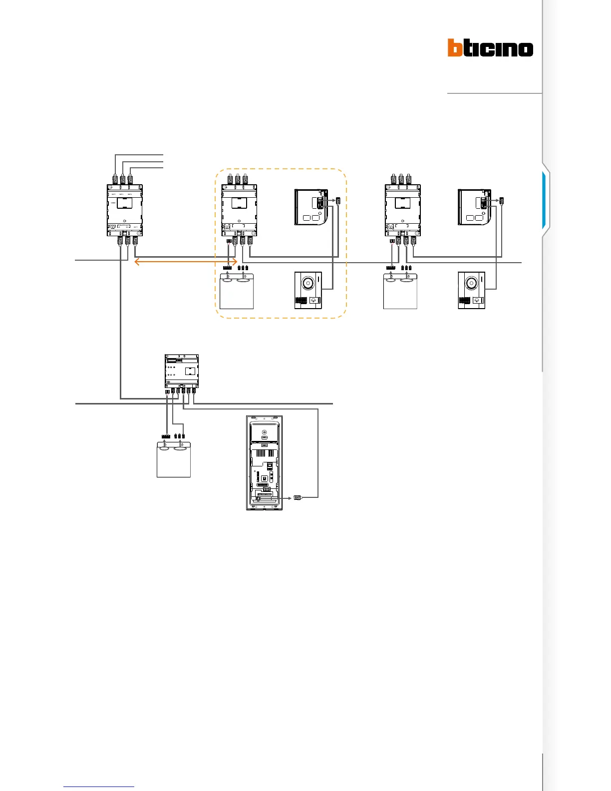
System wiring diagram of town villas.
323002 323002
323010 323010
SEP SEP
HANDSET HANDSET
323016
Floor Shunt 323002
MAX 200 m
323003
323005
EP
Riser Shunt
323003
Riser Shunt
323003
Villa Shunt
323016
n Power options: You can select the 323010 for 323002
power supply according to the actual power consumption
and the distance between Villa shunt and Floor shunt.
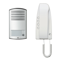
n For town villas not tted with Small EP, if there is 1 handset
in each villa, then connect the handset to the Floor shunt.
One Floor shunt is used for one house. If there are 2 to 5
handsets in one house, one Apartment Interface should
be connected to the Floor shunt HANDSET port for
expansion. All the handsets will connect to the Apartment
interface, and One Floor shunt must be used for each
house.
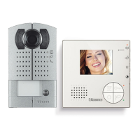
n For town villas tted with the Small EP, the installation is
just the same as that for the detached villas.
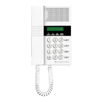
n The distance between the oor shunt and the handset
must be less than 50 meters and the oor shunt can only
be used for one villa.
n The maximum distance between Villa shunt and Floor
shunt can reach 200 meters, but on the precondition that
the maximum distance from the furthest video source
(like main EP) to the furthest video terminal (like HANDSET
and management centre) must be 1000 meters for the
colour system and 2000 meters for the B&W systems.
n To ensure correct operation of Villa shunt and Floor shunt,
their power source must be congured following the
software calculation results.

 Loading...