105
D45 VIDEO DOOR ENTRY SYSTEM
b
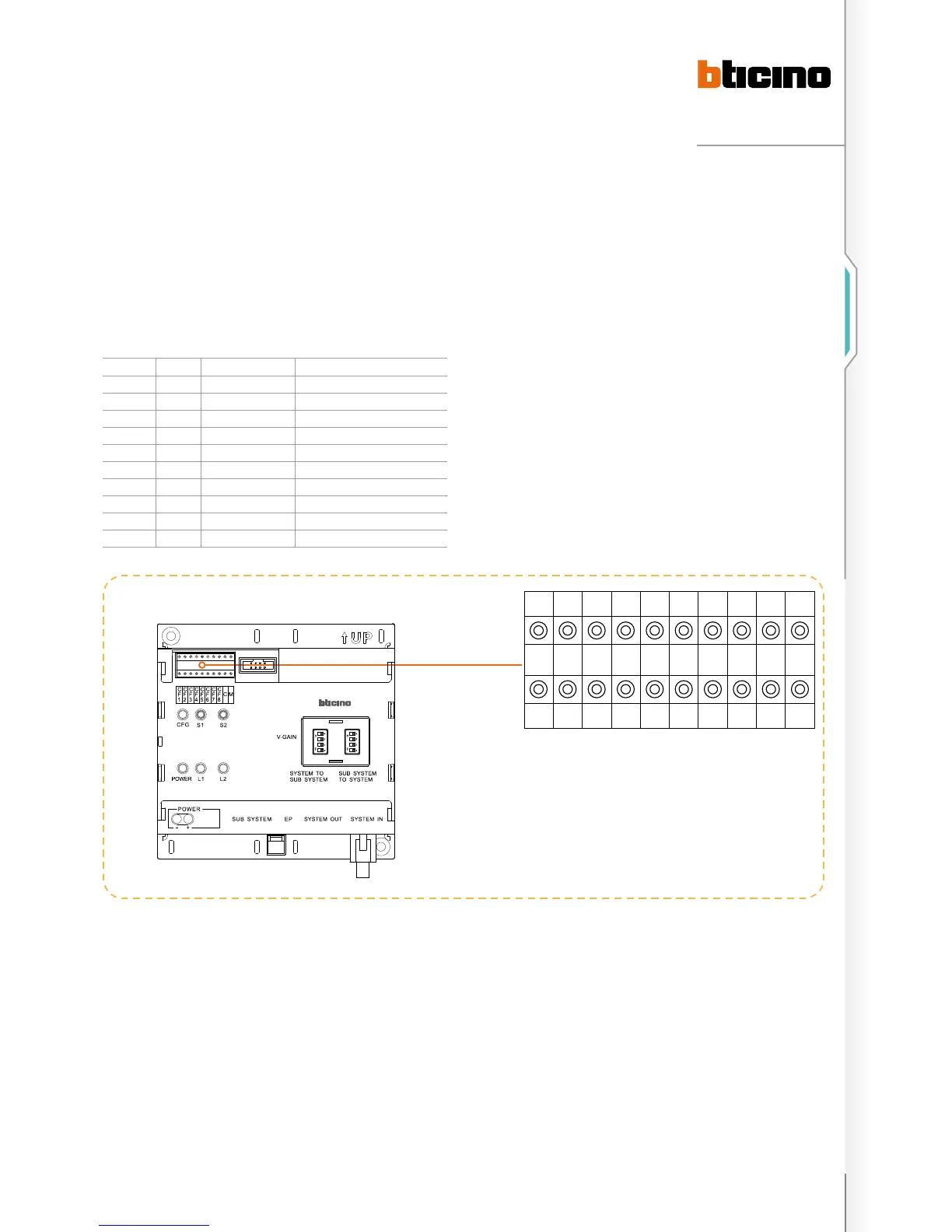
CF1 CF2 CF3 CF4 CF5 CF6 CF7 CF8 C M
N N N N #F #F #I #I C M
0 0 0 5 2 2 2 8 0 0
ON
SD
1
2
3
4
ON
SD
1
2
3
4
Example (B):
The number of riser shunts is 5, each riser has 25 floors, and
each floor has 8 handsets. The Switchboard that can be called
directly by this riser is no. 2 System configuration mode 2 is
used. The riser shunt configuration should be as follows:
POSITION MODE 1 VALUE FOR CONFIG. REMARKS
CF1 N 0 It is ok not to insert congurator 0
CF2 N 0 It is ok not to insert congurator 0
CF3 N 0 It is ok not to insert congurator 0
CF4 N 5
CF5 #F 2
CF6 #F 5
CF7 #I 0 It is ok not to insert congurator 0
CF8 #I 8
C C 0 It is ok not to insert congurator 0
M M 0 It is ok not to insert congurator 0

 Loading...