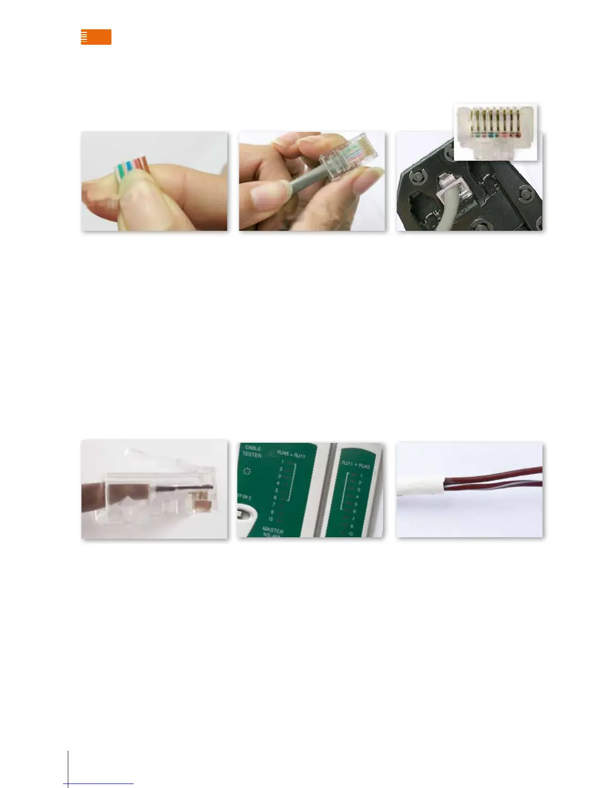
Step 5: Hold the RJ-45 connector
between your fingers with the copper
connectors face up. Slide the wires
into the connector, ensuring that each
coloured wire goes into its matching
slot. Push the connector firmly against
the wires.
Step 6: Before lock the wires inside the
connector, check from the top of the
connector to see that each wire is tightly
connected to the copper connector.
Step 7: after the final check, Place the
attached RJ-45 connector into the wire
crimping tool. Squeeze the crimper
handles down to lock the wires in place
inside the connector. When squeezing,
a “click” sound should be heard.
The following picture shows a correctly
fitted connector.
Step 8: test the cable.
Connect the two RJ45 connectors to the
tester. Turn on the test. The two groups
of lights will be flashing. If the 8 lights
turn to green one by one, it means the
cable is correctly assembled. Any red
lights or yellow lights indicate an open
circuit or bad connection.
Two wire cables must be used in the
following conditions:
1. System power supply connection to
floor shunt (323002)
2. Addition power supply connection
to Floor shunt
3. P18V connection to IT1 P18V
4. EP/ Backbone/main EP connection
to door lock, EP/ Backbone/main EP
connection to door lock and door
lock connection to power supply
Type DC-loop: 2x1.0 mm²
Resistance: 39.4/1km
RJ45 connections

 Loading...