Modules and their functions
5
Logamatic 4323 - Subject to technical modifications.16
U terminals 1 – 4
External set values can be received or issued via
the
U terminals of the ZM433 central module.
U terminals 1 (-) and 2 (+), 0 – 10 V input
Via terminals U1 and U2 on the ZM433 central module,
a 0 – 10 V signal can be externally applied to provide
a
set value.
This set value represents a further external heat
demand. Higher set values, e.g. from heating circuits,
continue to be taken into consideration.
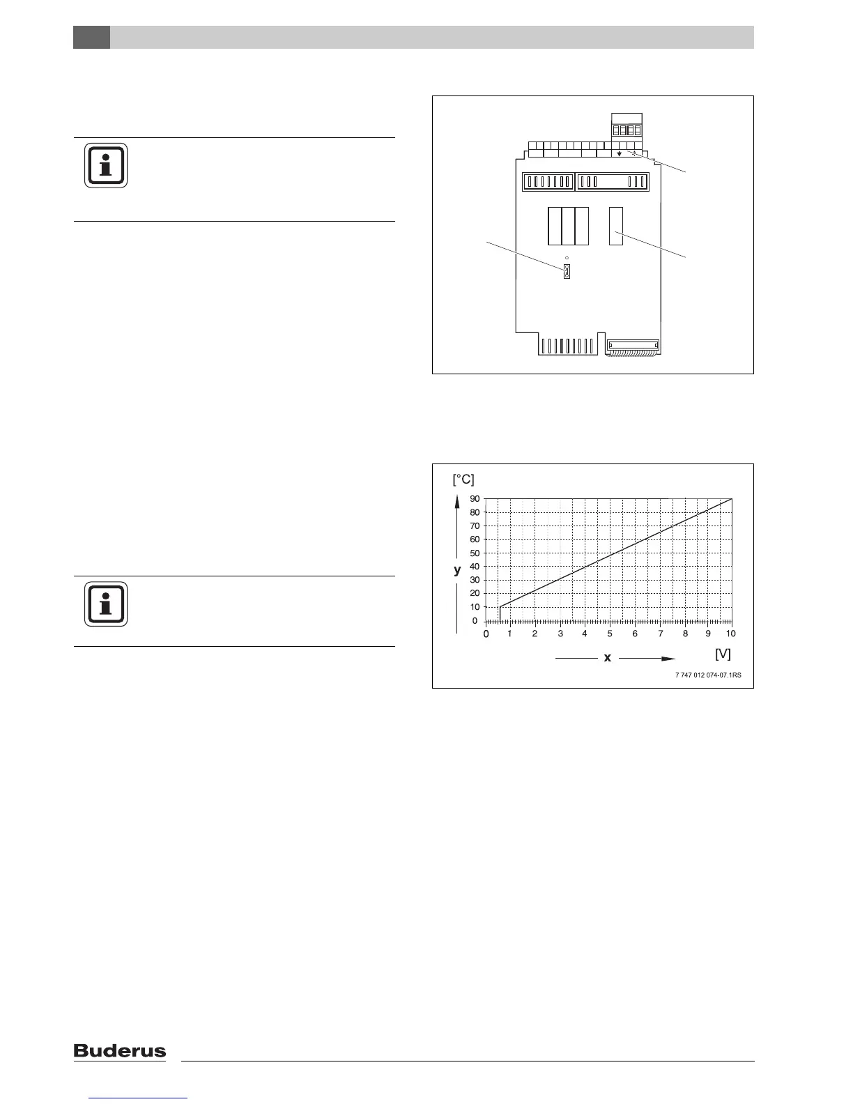
Fig. 9 ZM433 (view from the back)
1 Strapping plug J 1 (factory setting 0 – 10 V)
2 U terminals
3 Relay
USER INFORMATION
To avoid generating undefined input
values, voltages greater than 10 V must
not
be applied to the 0 – 10 V input.
Fig. 10 U terminals 1 and 2
x 0 – 10 V input in V (factory setting)
y Set flow temperature in °C
USER INFORMATION
You can adapt the curve if required
(
Æ Chapter 9.7).

 Loading...


