EasyManuals Logo

Buderus Logamatic 4323 Service Instructions

Buderus Logamatic 4323
124 pages
To Next Page IconTo Next Page
To Previous Page IconTo Previous Page
Page #17 background imageLoading...
Page #17 background image
Modules and their functions
5
Logamatic 4323 - Subject to technical modifications. 17
U terminals 3 (-) and 4 (+), 0 – 10 V output
Via terminals U 3 and U 4 on the ZM433 central module,
a 0 – 10 V signal can be supplied externally to provide
a
set value.
This would be the maximum system flow temperature
for
all connected heating circuits.
Strapping plug J1
Alternatively, the set value can also be issued as
0 – 20 mA signal.
The strapping plug (jumper) J1 should then
be
repositioned from to .
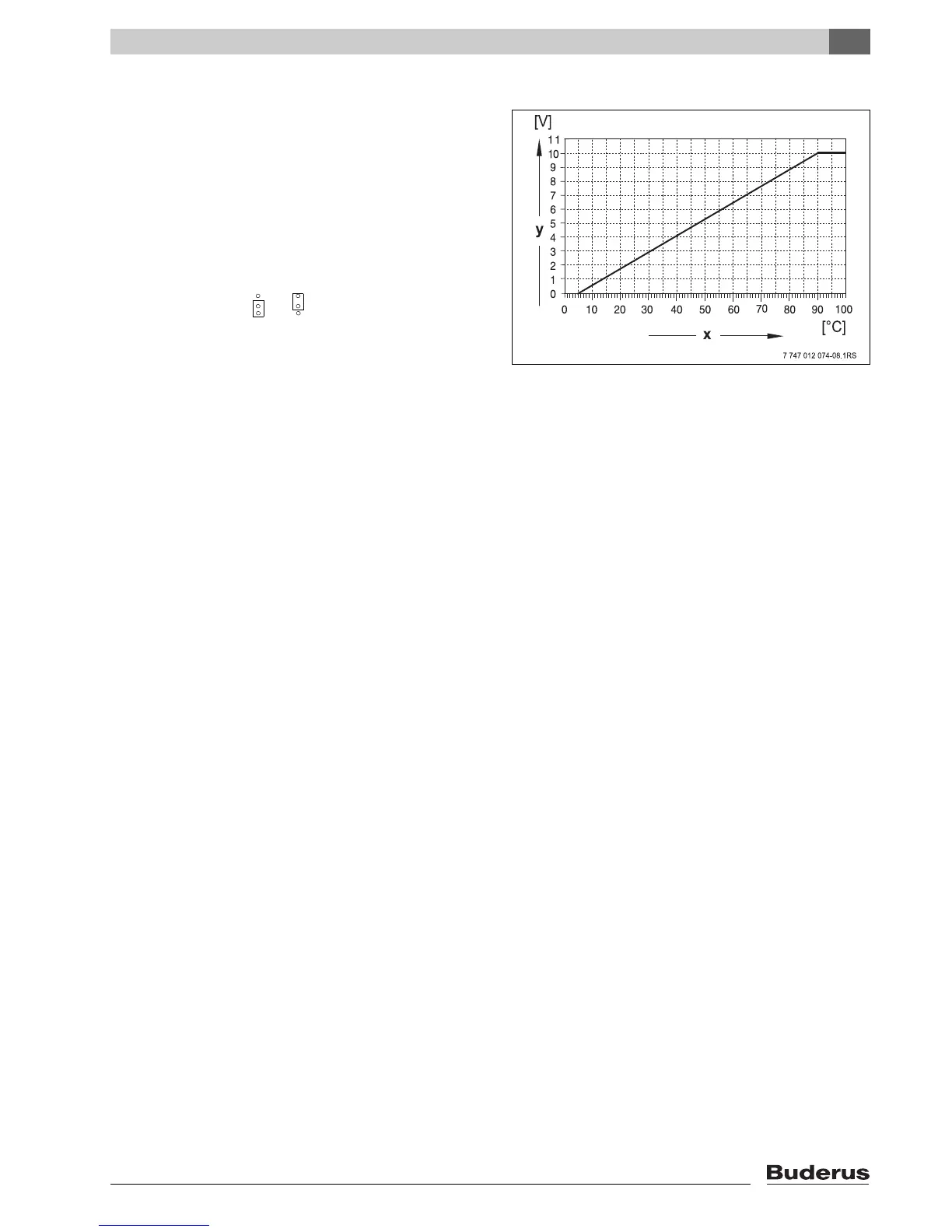
Fig. 11 U terminals 3 and 4
x Set flow temperature in °C (factory setting)
y 0 – 10 V input in V

Table of Contents

Other manuals for Buderus Logamatic 4323

Questions and Answers:

Question and Answer IconNeed help?

Do you have a question about the Buderus Logamatic 4323 and is the answer not in the manual?

Buderus Logamatic 4323 Specifications

General IconGeneral
BrandBuderus
ModelLogamatic 4323
CategoryControl Unit
LanguageEnglish

Related product manuals