2006 Buell Lightning: Engine 3-23
HOME
19. Remove cable strap securing wire bundle to return oil
line.
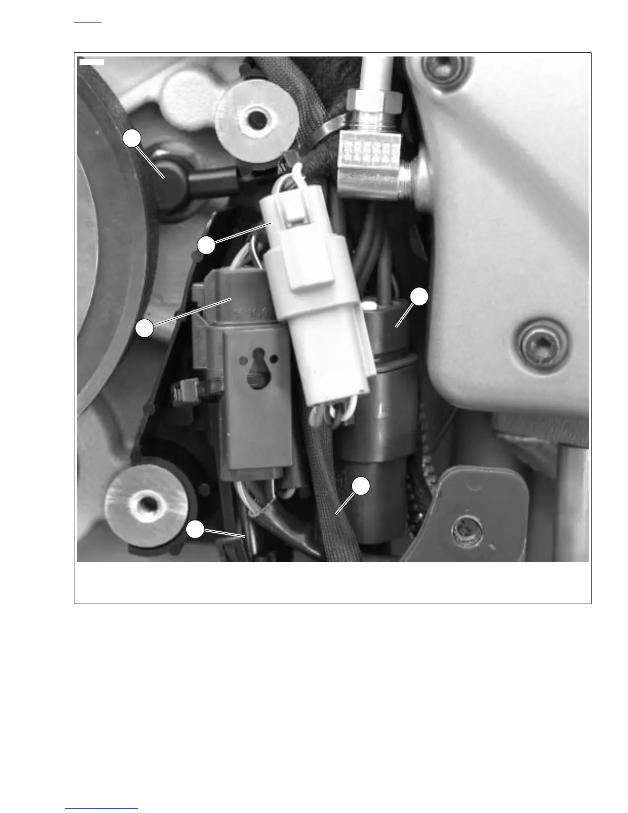
20. See Figure 3-18. Disconnect electrical components:
a. Neutral switch [131].
b. Speedometer sensor [65] (remove cable strap).
c. Cam position sensor [14].
d. Positive battery cable at starter.
e. Starter solenoid [128].
f. Oil pressure switch [120].
g. Alternator connector [46].
h. Voltage regulator connector [77].
21. See 3.10 OIL LINE FITTINGS. Remove all oil lines
(including lines to oil cooler).
22. See Figure 3-17. Remove vent oil line (2).
a. Disconnect vent oil line (2) at gearcase cover.
b. Remove clamp (13) in front of starter securing vent
oil line to return oil line.
c. Disconnect vent oil line at swingarm/oil reservoir (1)
and remove. See 3.10 OIL LINE FITTINGS/
REMOVAL.
Figure 3-18. Electrical Connectors Under Sprocket Cover
1. Neutral switch [131]
2. Speedometer sensor connector [65]
3. Cam position sensor connector [14]
4. Alternator connector [46]
5. Voltage regulator connector [77]
6. Interactive exhaust cable
4
5
3
11970b
1
2
6