2006 Buell Lightning: Electrical 7-7
HOME
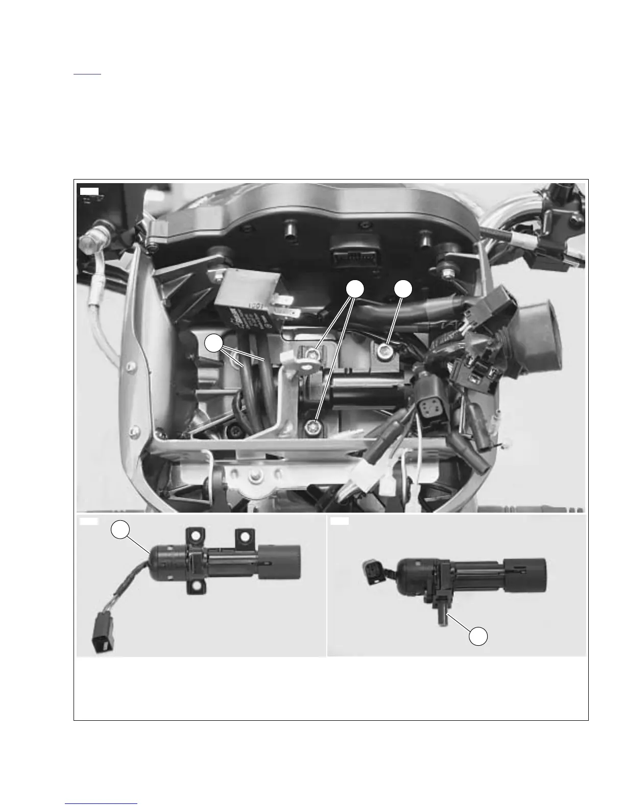
7. See Figure 7-4. Use Snap-on Tamper-Resistant T45 Torx
driver (Part No. FTXR45E) to remove the two tamper-
resistant Torx fasteners (2) securing ignition switch to
upper fork clamp.
8. Remove the final ignition switch fastener (1) along with
spacer located behind the ignition switch.
9. While holding the throttle cables (3) to your left (the right
side of the vehicle), pull the ignition switch (4) toward you
and roll the assembly away from you until the fork stop
pin (5) is pointing down.
10. Slide the ignition switch assembly out to your left (the
right side of the vehicle).
Figure 7-4. Ignition Switch (Typical)
1. Socket head fastener (1), with spacer behind switch
2. Tamper-resistant Torx fasteners (2)
3. Throttle cables
4. Ignition switch as positioned on vehicle
5. Fork stop pin (retracted)
2
4
5
1
3
8899
8904
8902