MicroDock II
User Manual
54
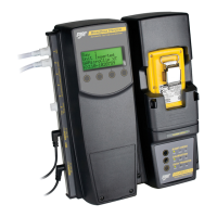
20. Successful Reconfiguring: If reconfiguration is successful, the
following screen displays.
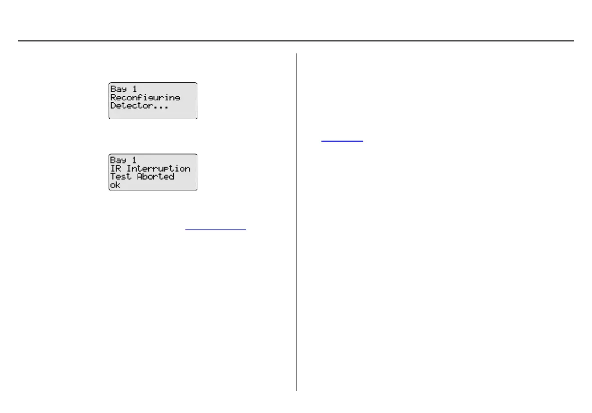
Unsuccessful Reconfiguration: If reconfiguration is not suc-
cessful, the following screen displays.
Press
C ok. The LCD then returns to normal operation.
Resolving IR Errors: Refer to the following solutions. If the following
solutions do not resolve the IR error, refer to Troubleshooting
.
• Check the lighting conditions. Infrared or intense light (sunlight or
halogen) can cause IR disruptions.
• Remove and reposition the detector in the docking module.
• Communication between the detector and base station may have
been temporarily disrupted. Complete the procedures again.
Gas Conflicts
When performing a bump test or calibration, gas must be applied in a
specific order to prevent gas conflicts that can damage the detector’s
sensor(s).
Note
Ensure that the gas inlets are configured correctly. Refer to
Inlet Select
.
The gas conflicts screen automatically displays if a gas conflict occurs
when a bump check or calibration is initiated.
There are two types of gas conflicts:
• Conflicts: More than one inlet is configured for a specific gas
type.
Example: Inlet 2 is configured for SO
2
and inlet 3 is configured
for the 3-gas SO
2
mix.
• Not Found: The base station is unable to locate the required gas
type for a specific sensor on the detector.
The base station displays additional information regarding the
• number of gas conflicts,
• number of gases not found,
• docking module (e.g., Bay 1),
• detector gas type(s),
• inlet, and
• inlet gas type(s).