3/4 in. conduit connection for
input/output & communications
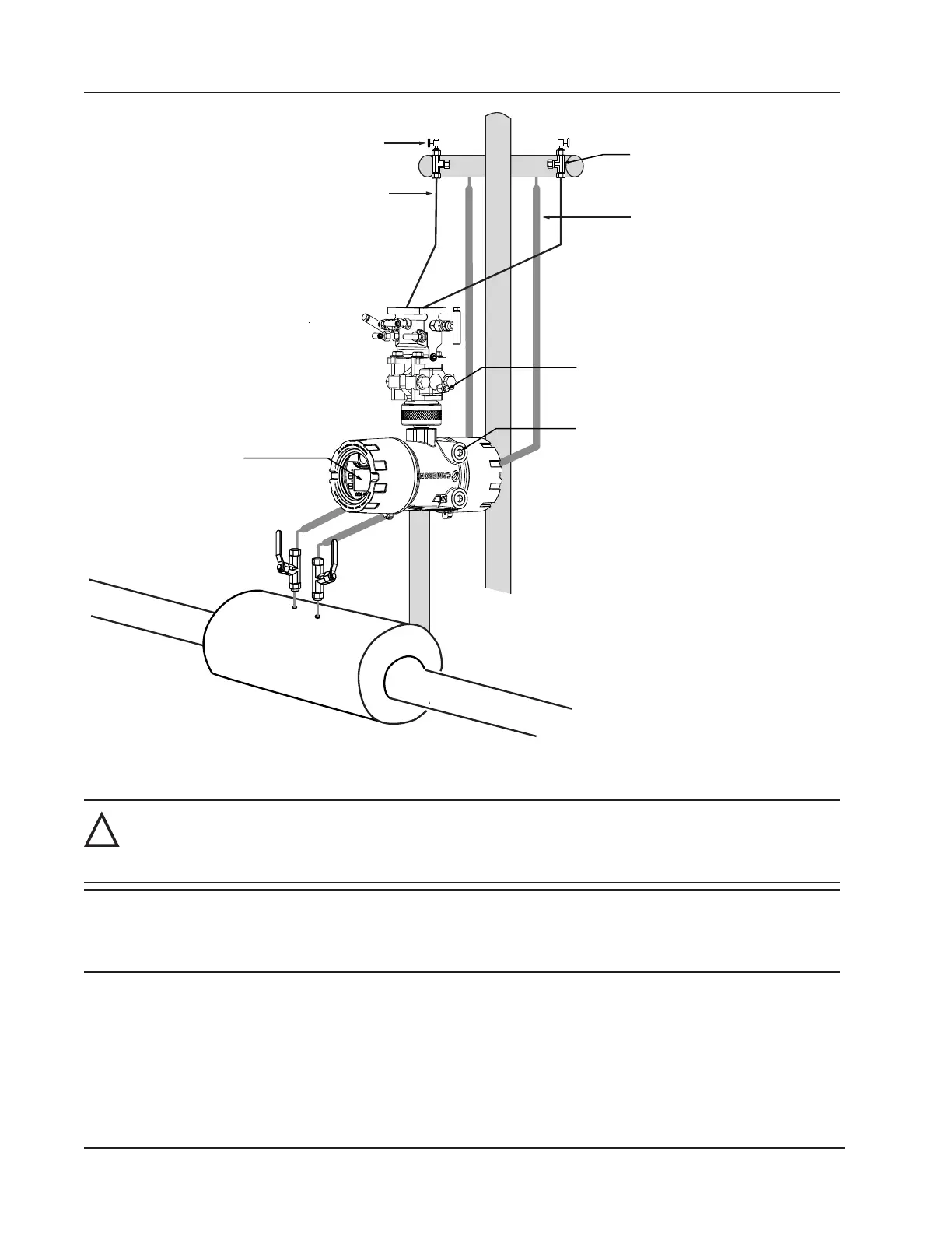
Cold legs connect to manifold
(slope to eliminate air trap)
Condensate pot (pipe tee
with blowdown valve attached)
Long cold legs protect the sensor from
extreme process temperatures
Hot legs, insulated to within
1 ft of condensate pot
(1/2 in. diameter recommended)
Pipe tee (can be used to fill cold legs)
LCD orientation
auto-corrects when
device is inverted
MVT vent (can be used to fill cold legs)
Figure 2.12—Remote-mount steam run installation
!
WARNING: HAZARDOUS AREA USE. The Scanner 3100 is certied for hazardous area use only when
installed in accordance with applicable standards and local wiring practices. Carefully review
Hazardous Area Precautions, page 27, to determine specic installation requirements (cable glands, con-
duit seals, signal cable, RTD, etc.).
IMPORTANT When measuring steam, process connections must be designed to eliminate air pockets. This is
achieved by making sure all tubing in the cold legs slopes upward. A bottom-port MVT and block
manifold (shown in Figure 2.12) is recommended to help prevent air bubbles from being
trapped in the sensor.
1. Verify that the meter is properly installed in the ow line (per manufacturer’s instructions).
2. Mount the Scanner 3100 to a 2-in. pipe or to a at, vertical surface using bolts and the mounting holes in the enclo-
sure. A horizontal pipe is recommended, as additional hardware may be required for a vertical pipe mount to provide
clearance for the manifold block.
44
Section 2 Scanner 3100 EFM