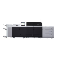
[Note] Make sure there is no gap between the upper/lower blade supports and the cleaner front side plate. Photo [A] is showing
that the cleaner front side plate is not inserted correctly, thus the shaft is seen and the bosses are not fitted. Photo [B] is the
correctly installed status without gap.
11) Assemble the parts by reversing the procedures from the step 8).
[Note] Note the followings when installing the parts.
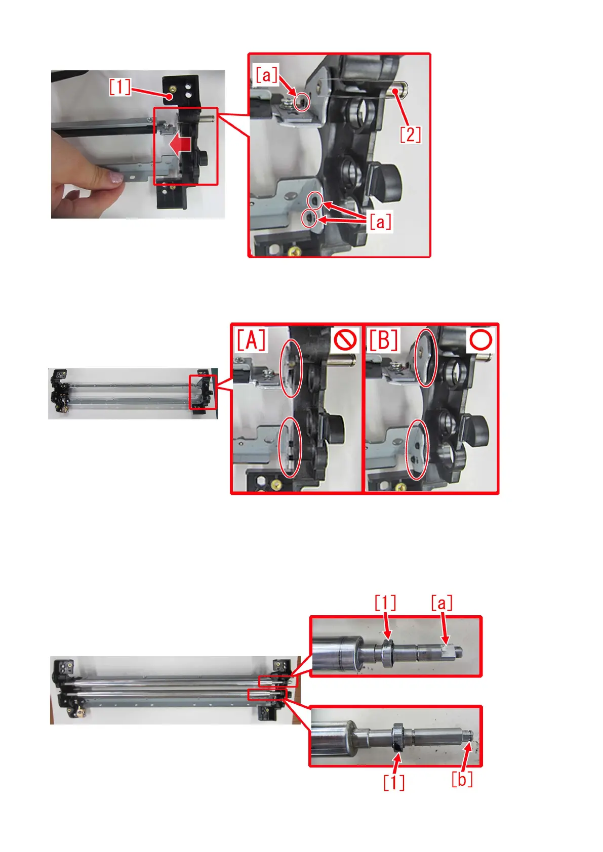
- Be careful with its orientation when installing a bias roller/bias roller 2 in step 7). The shaft end of a bias roller at the cleaner
front side plate side, has D cut [a]. The shaft end of a bias roller 2 at the cleaner front side plate side, has E ring groove [b]. Both
needs to have a bearing [1] attached, before installation.
80
 Loading...