COPYRIGHT © 1998 CANON INC. CANON PC400/420/430,FC200/220 REV.0 JAN.1998 PRINTED IN JAPAN (IMPRIME AU JAPON)
7-12
CHAPTER 7 EXTERNALS/AUXILIARY MECHANISMS
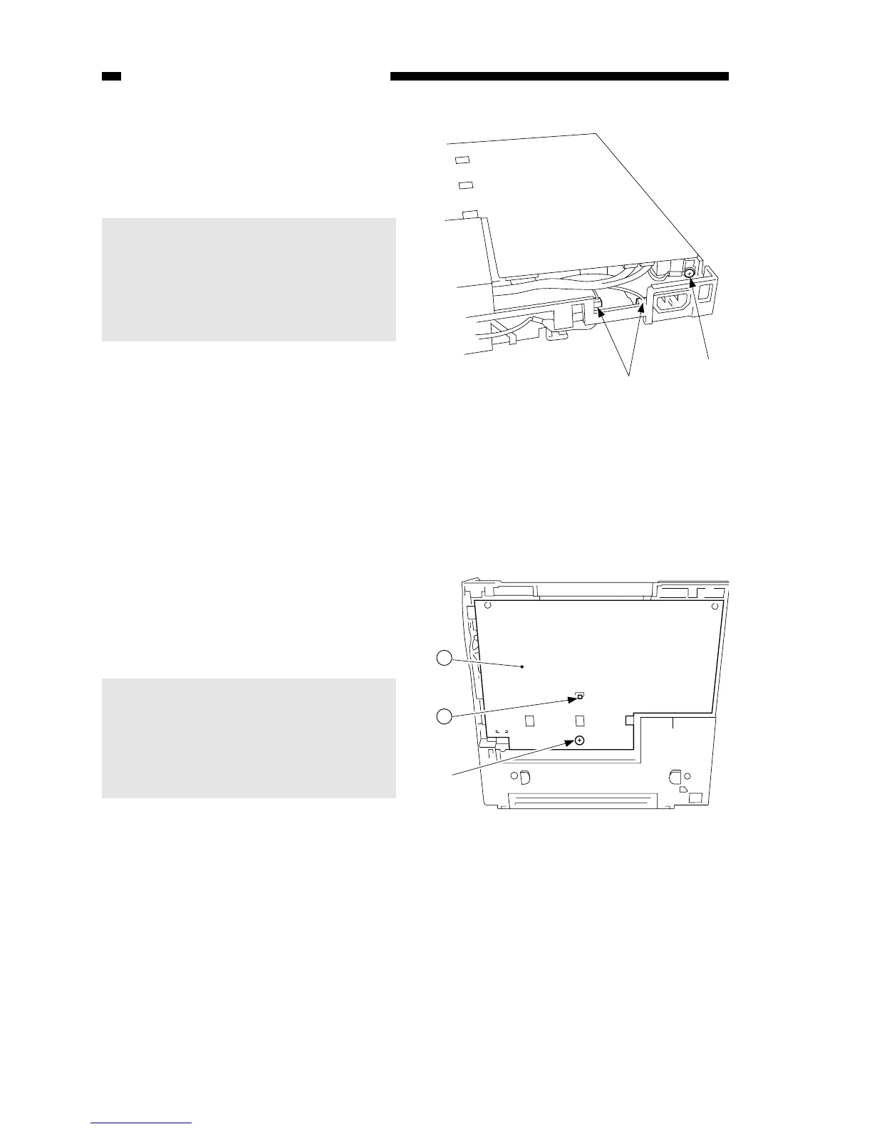
8) Disconnect the two connectors u at
the rear, and detach the grounding
wire i.
Caution:
The DC controller/DC power supply
PCB has high-voltage contacts and
pick-up sensor lever; take extra
care not to damage the parts when
detaching the PCB.
Figure 7-203C
Figure 7-204C
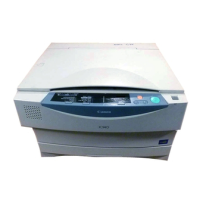
9) Remove the screw (M4X8; yellow)
o, and disengage the hook !0; then,
detach the DC controller/DC power
supply PCB !1.
Caution:
When attaching the DC
controller/DC power supply PCB,
make sure that lead wires are not
bitten or shorted, or the connectors
are not disconnected.