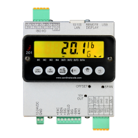
Model 201 Installation & Technical
8400-M117-O1 Rev D
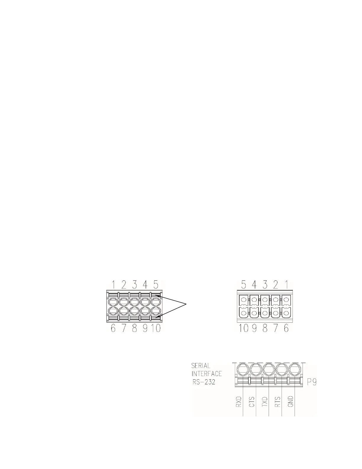
3.7 Serial and Analog I/O Cable Installation
3.7.1. The SERIAL and ANALOG I/O wires are to be connected to the P9
terminal block on the bottom panel of the weight transmitter. Refer
to Figure No. 2A for an illustration of the connector layout.
3.7.2. Remove the 10-connector terminal block connector from the weight
transmitter. Grasp the terminal block connector and lift straight up
away from the enclosure.
3.7.3. Referring to the table below and the labels on the enclosure for
terminal connections, connect each wire to the terminal block.
3.7.4. Remove 2" of the outer insulation jacket then remove 1/4" of
insulation from each of the wires.
3.7.5. To terminate a wire, push down on the orange spring loaded
plunger and then insert the wire into the terminal opening. Release
the plunger to secure the wire in place.
3.7.6. Repeat the procedure until all wires are in place.
P9 – Serial and Analog I/O Wiring Table
(Note: Must Select RS-232 or RS-485 in Serial Port Mode)
P9 Terminal Block
Connector
CPN - 6610-1548