3-CONTROLSANDINSTRUMENTS
NOTICE:Beforeremovingattachments,makesurethatyourelievepressurefromthehydraulicsystemBEFORE
disconnectingtheauxiliaryhoses.Ifthepressureisnotrelieved,youWILLNOTbeabletoreattachhoses.The
highow5/8inchquickdisconnectsonthemachinedonothavetheabilitytorelievepressurewhenconnectingor
disconnecting,butthefollowingprocedureshowshowtoreleasethepressure.
Relievepressurebeforedisconnectingat-
tachmenthoses
1.Lowertheloaderarmallthewaydownandensure
thattheloaderarmorattachmentisnotsupporting
theweightofthemachinewiththefrontwheelsoffthe
ground.
2.Placeallcontrolsintheneutralposition.
3.PresstheOperatebuttontodeactivatethehydraulic
systemandgrounddrivesystem.
4.Stoptheengine.
5.Movethecontrolstoensurethatthehydraulicinterlock
isengagedandtheloaderarmandbucketcylindersdo
notmove.
6.Raisetherestraintbar,unfastentheseatbelt,and
safelyexitthemachine.
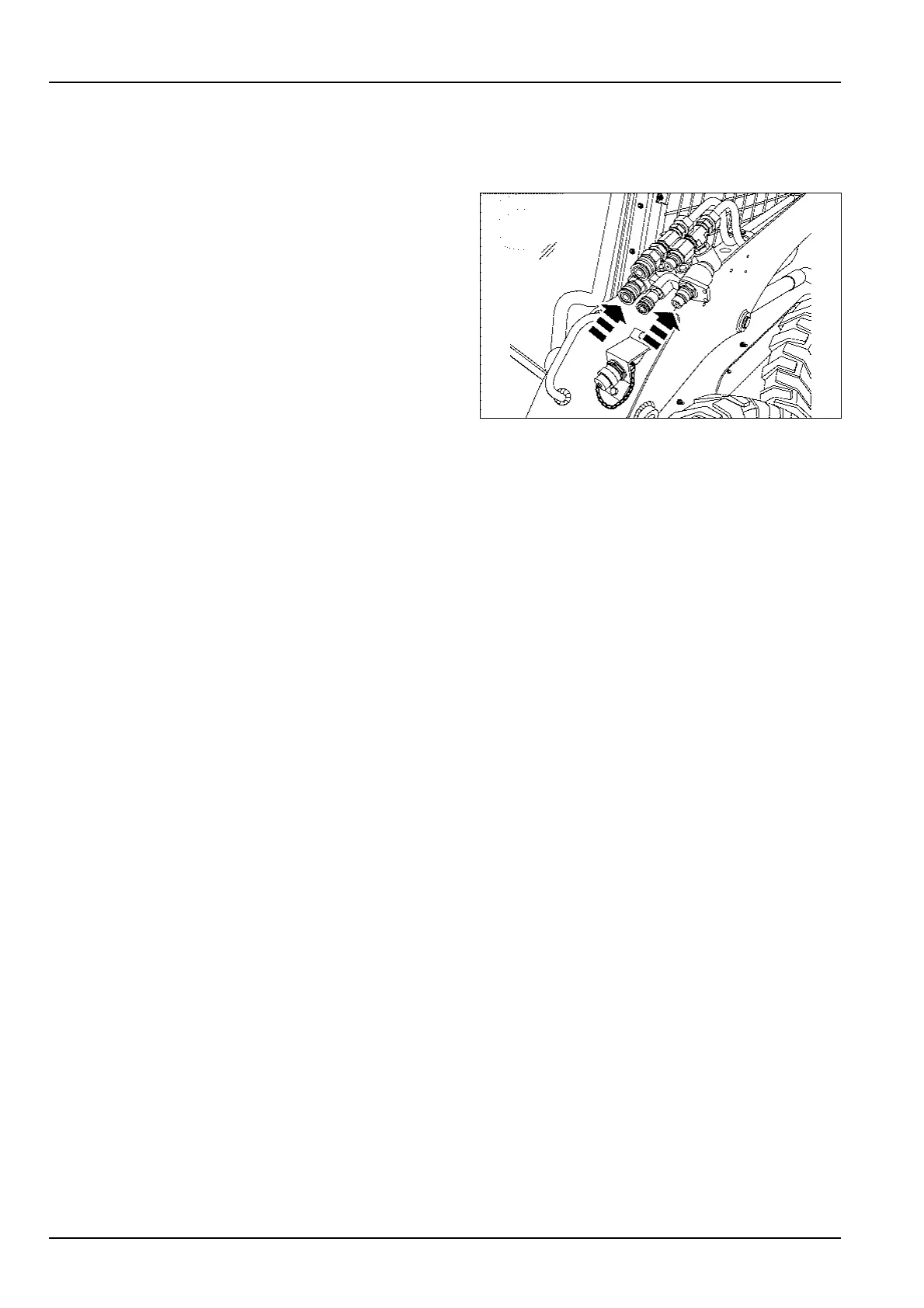
7.Priortodisconnectingthe5/8inchhighowattach-
menthoses,withthepalmofyourhandpushoneof
thelower,1/2inchquickdisconnectcouplingstowards
theConnect-Under-Pressure(CUP)valve.When
doneproperly,thecouplingwillmoveabout6mm
(0.25in),relievinganystoredpressureinthatcircuit.
8.RepeatStep7ontheother1/2inchcoupling.
93106839B3
9.Disconnectthe5/8inchhighowattachmenthy-
draulichosesfromthequickdisconnects.
10.Installthecouplercovers,ifequipped.
3-32