Cellwatch Frontier System Installation & User Manual
Section I – Installation Guide-46
In Frontier, one or more channels can be specified as an inter-cell link, an inter-tier link, or a charger
cable. Frontier will separate these channel readings from cell readings in order to provide better scaling
with graphs while still allowing the link(s) to be monitored. A DCM unit equipped with Extended Leads
can be used to monitor long inter-tier links.
Inter-cell and Inter-tier straps
Inter-cell straps and links can be monitored by modifying the DCM wiring. This allows the user to
monitor for changes in torque or degradation of the connection between posts.
Additional hardware is needed to monitor straps separate from cells. NDSL provides terminal (post) clips
that must be installed onto each container terminal to obtain accurate ohmic value readings for each
link. See the next section for additional post clip information.
In this configuration, power leads are connected to ring tabs while sense leads are connected to
terminal clips. Ring tabs are placed on the bolt of every other (odd numbered) terminal post, starting
with the positive post of the first container in the string.
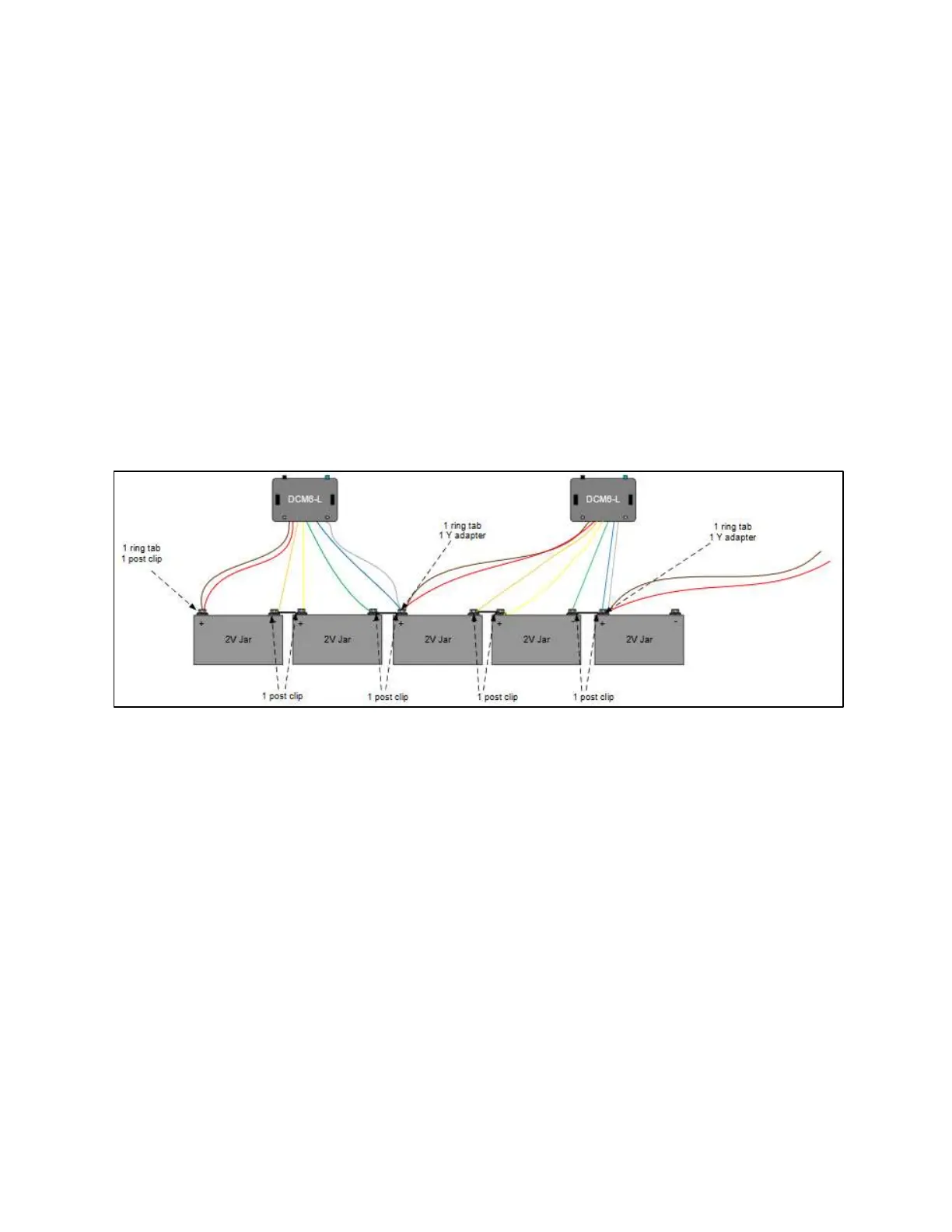
Example DCM 6 wiring for measuring straps and cells separate.
The power leads (brown and white, shown above) are extended across two 2V containers for each DCM
to provide enough voltage to power the DCM. A Y-tab connector may be used to get additional sense
leads onto one connection point.