Cellwatch Frontier System Installation & User Manual
Section I – Installation Guide-52
DC bus cables
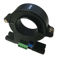
DC bus cables can be monitored for continuity and variance. This requires two DCM6-L-CC units that
connect from the positive of the DC power supply to the positive of the battery and the negative of the
DC power supply to the negative of the battery. Channel one of each CC unit is used for the
measurement (between the red and orange leads).
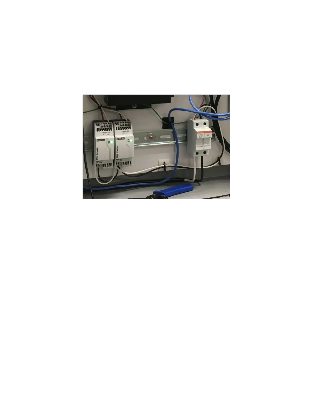
DC power supply units used to power the DCM6-L-CC mounted inside Frontier enclosure.
Incorporate the DCM6-L-CC into the fiber loop with the DCM6-L or DCM5 string. Standard designs are to
locate the DCM6-L-CC as the last two DCMs or as the first and last DCM units in the loop. Connect the
power leads to the 5 VDC External Supply.
Orange and white leads will connect to ring tabs on a clamp or other connection point along the charger
cable. Ensure the orange and white leads are connected to separate ring tabs (Do not use a single ring
tab and Y adapter for these connections).