CG Drives & Automation, 01-5326-01r5 Installation 33
3. Put the two lower cables (Mains 1 and Motor 1
cables) through the lower glands in the cable
interface plate.
4. Strip the cables according to Table 17 and Fig. 55.
5. Connect the cable lugs to the stripped cable ends.
6. Connect the cable lugs to respective mains and
motor terminal bolts.
7. Fix the clamps on appropriate place and tighten the
cable in the clamp with good electrical contact to
the cable screen.
Fig. 47 Upper mounting rail mounted over the lower cables.
Continue with the upper mains and motor cables (marked
Mains 2 and Motor 2 in Fig. 48).
1. Mount the upper mounting rail over the lower,
connected cables (Mains 1 and Motor 1 cables) at
same place as before, with the four screws.
2. Put the two upper cables (Mains 2 and Motor 2)
through the glands in the cable interface plate.
3. Strip the cables according to Table 17 and Fig. 55.
4. Connect the cable lugs to the stripped cable ends.
5. Connect the cable lugs to respective mains/motor
terminal bolts.
6. Fix the clamps on appropriate place and tighten the
cable in the clamp with good electrical contact to
the cable screen.
7. Put the cable interface plate in place and secure
with the fixing screws.
Fig. 48 All cables and cable clamps connected.
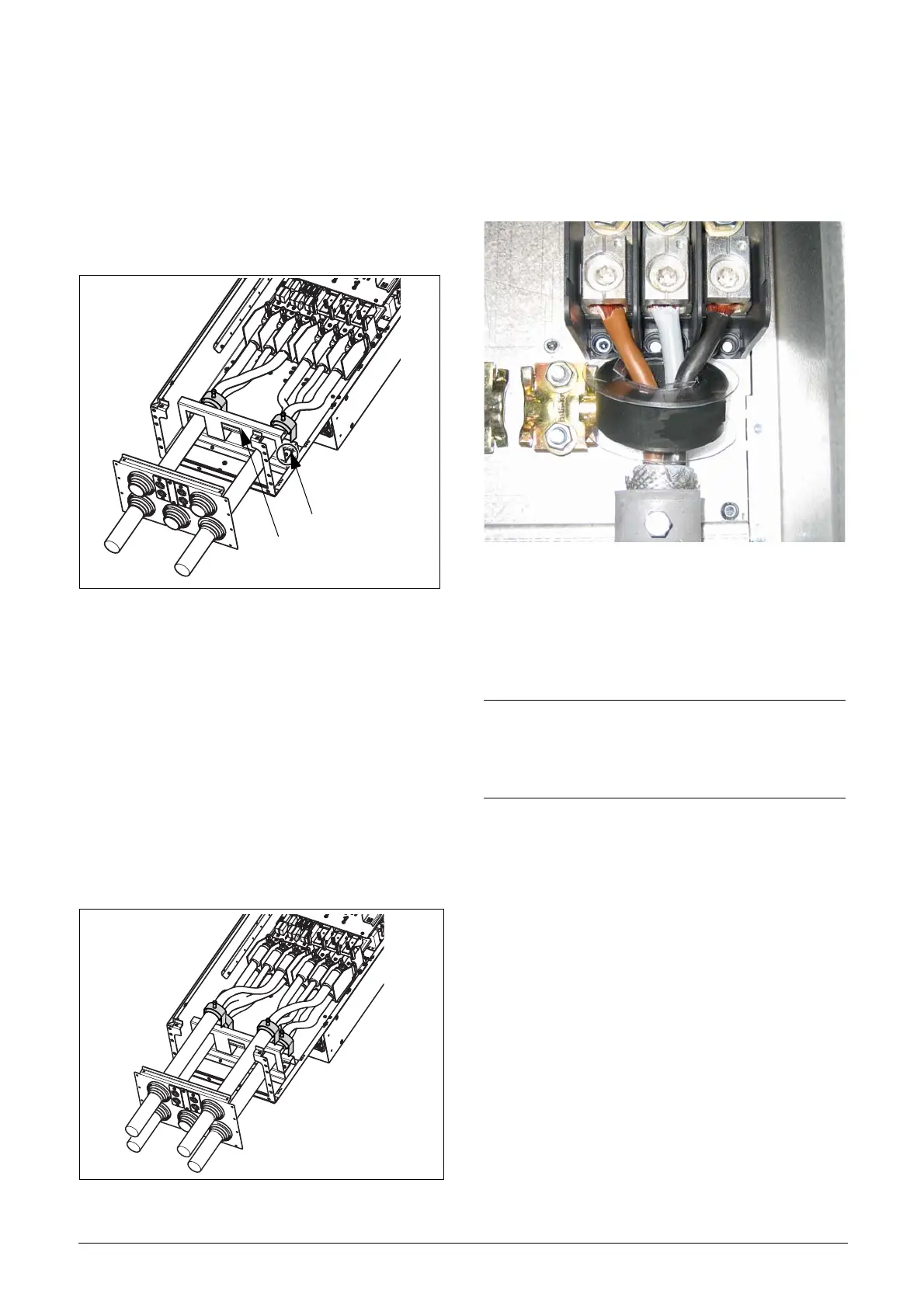
Emotron VFX48-090 mount extra ferrite
core
Mount the ferrite core and its isolation sheet (included in
the delivery) on the three motor phases U,V &W.
The protective earth (PE) and the screen of the cable should
be mounted outside the core see Fig. 49.
Fig. 49 Ferrite core mounted on the motor cables
The ferrite core is mounted on the motor cable to reduce
disturbances and to fulfil the EMC standards. Since the core
becomes very hot, the cables must be protected by a thermal
isolation sheet that is attached on the core. The longer
motor cables the hotter the core becomes.
Mains 1
Motor 1
Motor 2
Mains 2
NOTE: If the core is not mounted or mounted
incorrect, the AC drive does not fulfil the EMC
standards. If the protective isolation sheet is not
mounted, the motor cable can be damaged from the
hot core.

 Loading...