EasyManuals Logo
Home>Cisco>Network Router>ASR 5000 Series

Cisco ASR 5000 Series User Manual

Cisco ASR 5000 Series
992 pages
To Next Page IconTo Next Page
To Previous Page IconTo Previous Page
Page #954 background imageLoading...
Page #954 background image
Technical Specifications
â–€ Interface Specifications
â–„ Cisco ASR 5000 Series Product Overview
OL-22938-02
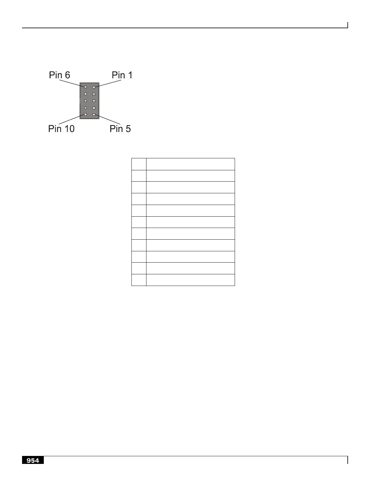
Figure 222. SPIO CO Alarms Interface Pin-out
Table 110. SPIO CO Alarms Interface Pin-out
Pin
Signal
1
Major Alarm - Normally closed
2
Major Alarm - Common
3
Major Alarm - Normally open
4
Minor Alarm - Normally closed
5
Minor Alarm - Common
6
Minor Alarm - Normally open
7
Critical Alarm - Normally closed
8
Critical Alarm - Common
9
Critical Alarm - Normally open
10
Not Used
The 8-foot CO alarm cable shipped with the chassis supports redundant SPIO card installations. The CO alarm cable is a
―Y‖ cable, with two connectors on one end. Each connects to one of the SPIO cards. On the opposite end is a 9-pin
terminal block that you can mount to the telco cabinet or equipment rack frame. The figure shows the CO Alarm cable.
The following table provides the CO Alarm cable pin-outs.

Table of Contents

Other manuals for Cisco ASR 5000 Series

Questions and Answers:

Question and Answer IconNeed help?

Do you have a question about the Cisco ASR 5000 Series and is the answer not in the manual?

Cisco ASR 5000 Series Specifications

General IconGeneral
BrandCisco
ModelASR 5000 Series
CategoryNetwork Router
LanguageEnglish

Related product manuals