Appendix C Connecting to DC Power
Grounding the Switch
C-4
Catalyst 2950 Desktop Switch Hardware Installation Guide
78-11157-05
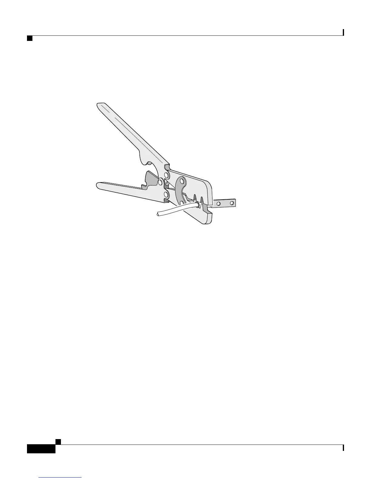
Step 4 Using a Panduit crimping tool, crimp the ground lug to the 6-gauge wire.
Figure C-2 Crimping the Ground Lug
Step 5 Use the two number-10-32 screws to attach the ground lug and wire assembly to
the rear panel of the Catalyst 2950G-24-EI-DC switch or to the front panel of the
Catalyst 2950ST-24 LRE 997 switch.
Step 6 Using a ratcheting torque screwdriver, torque each ground-lug screw to 15 lbf-in.
(240 ounce-force inches [ozf-in.]). Figure C-3 shows how to torque the ground
screws on a Catalyst 2950G-24-EI-DC switch.
60529