2-9
Cisco SCE8000 GBE Installation and Configuration Guide
OL-19897-02
Chapter 2 Introduction to the Cisco SCE8000 GBE Platform
Modular Optics
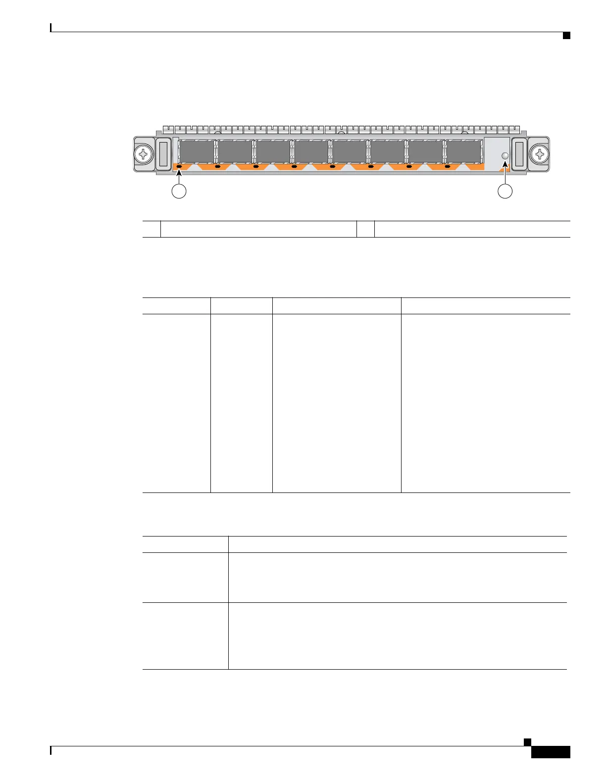
For an illustration of the 8-Port GBE SPA Interface Module refer to Figure 2-5.
Figure 2-5 8-Port GBE SPA Interface Module
Table 2-7 lists the SPA port information and Table 2-8 lists SPA LEDs and describes their indications.
1 A/L (Active/Link) LED 2 Status LED
129568
SPA-8X1GE-V2
3
4
STATUS
2
1
0
A
/L
5
6
7
A
/L
A
/L
A
/L
A
/L
A
/L
A
/L
A
/L
1 2
Table 2-7 SPA Ports
Port Quantity Description Connect This Port To…
GBE Line port eight on each
SPA
Any one of the following:
• SFP-GE-S
(1000BASE-SX SFP
(DOM))
• SFP-GE-L
(1000BASE-LX/LH SFP
(DOM))
• SFP-GE-Z
(1000BASE-ZX Gigabit
Ethernet SFP (DOM))
CLI designation: interface
TenGigabitEthernet 3/0/0-7,
3/1/0-7, 3/2/0-7, 3/3/0-7.
Any one of the following:
• Subscriber side network
component
• Network side network component
• Optical bypass GBE line port
• 10GBE line port of a cascaded
SCE8000 GBE platform
Refer to Connecting the GBE Line
Ports to the Network, page 6-2 for
further information.
Table 2-8 SPA LEDs
LEDs Description
Active/Link (1)
• Green —Port is enabled by software and the link is up.
• Amber — Port is enabled by software and the link is down.
• Unlit — Port is not enabled by software.
Status (2) The Status LED indicates the operational status of the SPA module, as follows:
• Green — SPA is ready and operational.
• Amber — SPA power is on and good, and SPA is being configured.
• Off — SPA power is off.