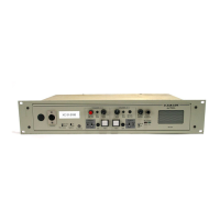
4.2.2 Installing the rear panels
The rear panel of the matrix is constructed of modular, individually-installable
connector panels. Each port or expansion card has a corresponding rear-
connector panel:
• An MVX-A16 rear panel has 16 RJ-45 connectors.
• E-FIB rear panels have two fiber connectors.
• E-QUE, IVC-32 and LMC-64 rear panels have 11 RJ-45 connectors.
• E-MADI64 rear cards have a MADI fiber connector, MADI input and
output coaxial cable connectors, and a coaxial Video / Word clock input.
Note: Clear-Com ships each matrix with the required number of rear-connector panels
already installed. Blank rear panels fill unused card slots.
To add a rear panel to the matrix:
• Remove the desired blank rear panel by loosening the screws and pulling
the panel out. The screws are attached and cannot be removed.
• Install the new rear panel by sliding the card into the card’s guides at the
top and bottom of the Eclipse HX-Delta chassis.
• Tighten all of the screws on the rear panel.
To remove a rear panel from the matrix:
• Detach any devices connected to the rear panel’s connectors.
• Loosen the screws that hold the rear panel to the matrix. The screws are
attached and will not fall off.
• Remove the rear panel by pulling the panel out.
4.3 Installing CPU cards
The CPU card’s components include CMOS chips which are sensitive to static
electricity. Before touching the CPU card touch a grounded metal object, such as
any unpainted surface on the matrix, to dissipate static electricity. While
handling the CPU card, be careful not to bend any of the card’s connector pins or
component leads.
Before operating the CPU card the card’s battery must be reconnected.
Note: The CPU card is shipped with a disconnected battery to preserve battery life. For
instructions on reconnecting the battery, see 4.1.3 Reconnecting the CPU
card backup battery in this document.
The CPU card switch settings for normal operation (watchdog enabled) are
shown in Figure 4-2: CPU card DIP switches set for normal operation