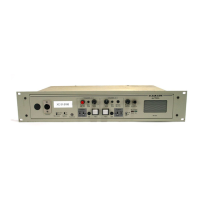
5.8.3 Connecting interface cards
Each rear-connector panel associated with an MVX-A16 (analog) interface card
holds the sixteen RJ-45 connectors that connect the matrix to user panels,
interface modules and other intercom devices. Each front-installed MVX-A16 port
card requires a corresponding rear-connector panel. Blank panels cover unused
slots.
Each port on the matrix can be located and identified by using the rear-panel
numbering grid:
• Port rows are numbered 1 through 16.
• Port columns are numbered 1 through 7.
• CPU card columns are numbered P1 and P2. (One rear panel operates
with either of the currently active CPU cards).
Note: A port can be identified precisely by identifying its card number
and port number on the card. For example, the ports on the first
card are designated 1-1, 1-2, 1-3, 1-4, and so on; the ports on
the second card are designated 2-1, 2-2, 2-3, 2-4, and so on.
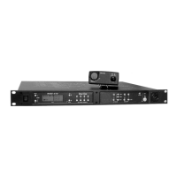
Each rear connector panel associated with an E-QUE interface holds eleven RJ-
45 ports:
• Eight ports for connection to wireless equipment.
• Two ports for DECT sync.
• One port for LAN connections.
Each rear connector panel associated with an IVC-32 interface holds eleven RJ-
45 ports:
• Eight ports for connection to E1/T1 equipment (not used).
• Two ports for DECT sync (not used).
• One port for LAN connections, used for IP-enabled V-Series panels and
Concert soft-panels.
Each rear connector panel associated with an LMC-64 interface holds eleven RJ-
45 ports:
• Eight ports for connection to E1/T1 equipment (not used).
• Two ports for DECT sync (not used).
• One port for LAN interface used for broadcasting audio levels to
Production Maestro Pro clients.
Each rear connector panel associated with an E-FIB interface holds two fiber
ports (TXVRA and TXVRB).
Note: For detailed information about connecting the matrix to user panels, interface
modules and other devices, see 4 Installing the Eclipse HX-Delta in this
document.