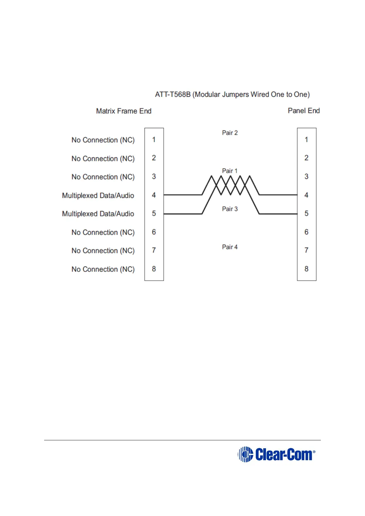
Pair 1 transmits and receives multiplexed digital and analog between the matrix
and the panel. Ensure that the Select switch on the rear of the panel is in the
correct position for the intended use.
Figure 4-7: Wiring the matrix to a digital panel using RJ-45
Note: Important. The above wiring diagram refers to DIG-2 and is shown as an
example only (DIG-2 panels are not compatible with the Eclipse HX-Delta.
4.7 Wiring CPU card interfaces
The CPU card holds the circuitry for connecting to, and communicating with, the
following interfaces:
• An external personal computer.
• Alarm inputs and outputs.
• Eight general purpose inputs (GPIs).
• Eight general purpose outputs (GPOs or relays).
• Two separate local area network (LAN) connections for Ethernet-based
communication with a network.
• An external GPI/RLY interface.