User Guide | Eclipse HX-Delta
products (21 CFR 1040.10 and 1040.11) except for deviations pursuant to Laser
Notice 50, dated July 26, 2001.
Normally a protective plug is fitted to the fiber connector to protect the
connector from damage or the entry of foreign materials. The protective plug
should only be removed in order to fit the fiber optic cable. Replace the plug
when the cable is unplugged.
Note: Primary and secondary fiber ports are reversed with respect to the front panel
indicators.
Care should be taken when connecting or disconnecting cables to ensure that
they are connected correctly and not reversed.
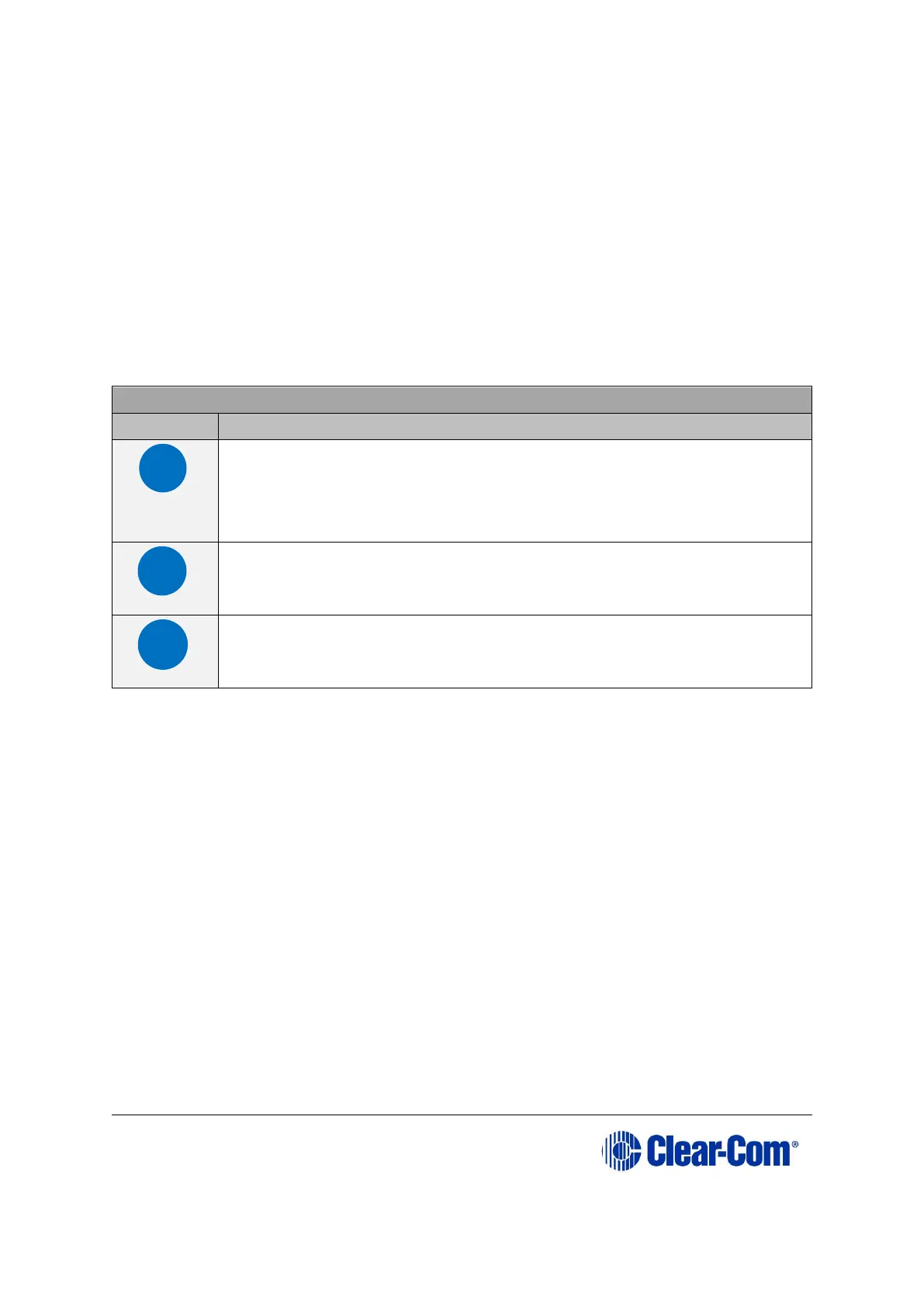
Key to E-FIB rear panel connectors
+3.3-Volt Power Supply LED
When this green LED is lit, the +3.3-volt power supply (supplied
by the matrix) is present and supplying electric current to the
card.
Fiber transceiver with Duplex LC type connector. The TXVRB
connector is used for the secondary ring.
Fiber transceiver with Duplex LC type connector. The TXVRA
connector is used for the main ring.
Table 7-2: Key to E-FIB rear panel connectors
The fiber optic cable for the primary and secondary circuits are plugged into the
appropriate ports. An example showing three systems configured with a primary
and secondary ring is shown in Figure 7-3: Primary and redundant ring
configuration.