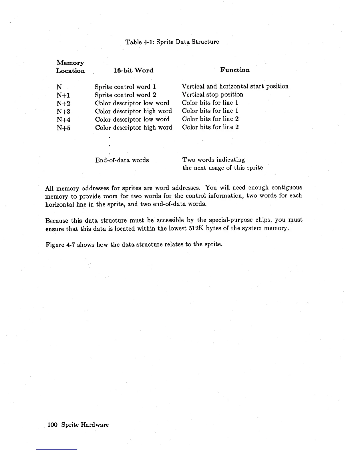
Table
4-1:
Sprite
Data
Structure
Memory
Location
N
N+1
N+2
N+3
N+4
N+5
16-bit
Word
Sprite control word 1
Sprite control word 2
Color descriptor
low
word
Color descriptor high word
Color descriptor
low
word
Color descriptor high word
End-of-data words
Function
Vertical and horizontal
start
position
Vertical stop position
Color bits for line 1
Color bits for line 1
Color bits for line 2
Color bits for line 2
Two words indicating
the next usage of this sprite
All memory addresses for sprites are word addresses. You will need enough contiguous
memory
to
provide room for two words for the control information, two words for each
horizontal line
in
the sprite, and two end-of-data words.
Because this
data
structure must be accessible by the special-purpose chips, you must
ensure
that
this
data
is located within the lowest 512K bytes of the system memory.
Figure
4-7
shows how the
data
structure relates
to
the sprite.
100 Sprite Hardware