Table
7-3:
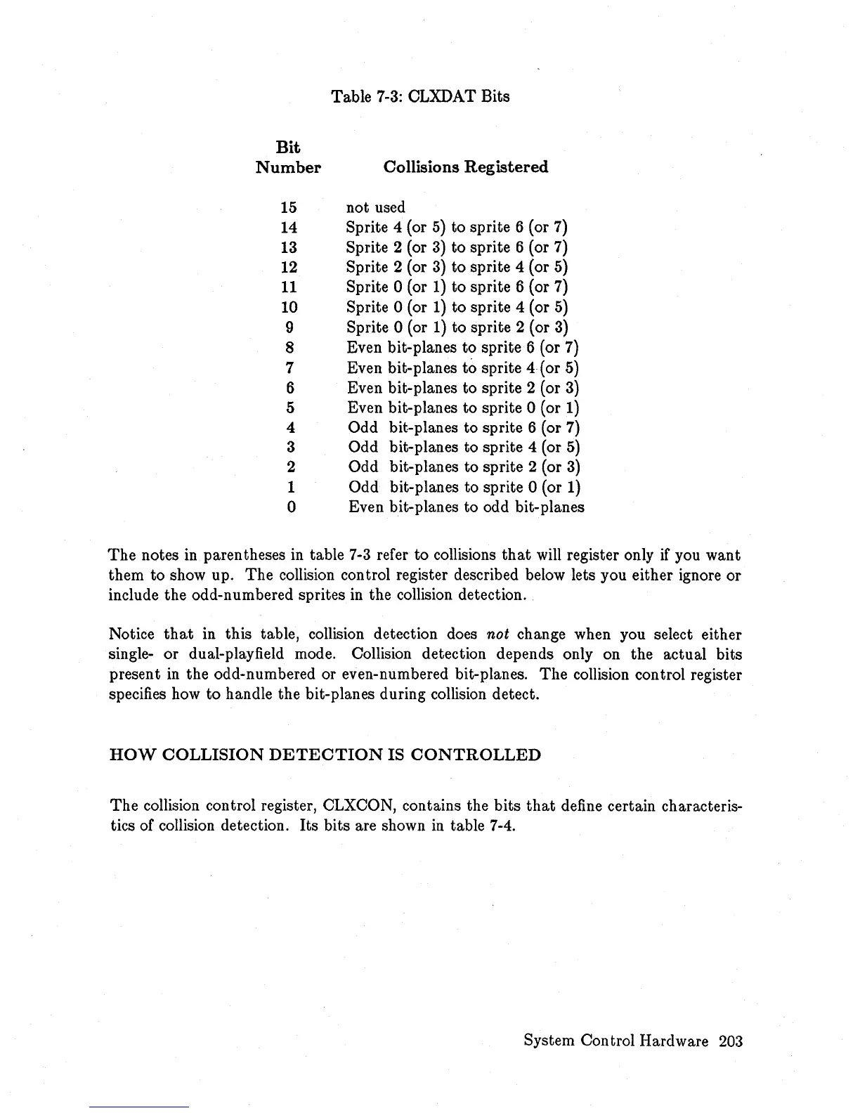
CLXDAT Bits
Bit
Number
Collisions
Registered
15
not used
14 Sprite 4 (or
5)
to sprite 6 (or
7)
13
Sprite 2 (or
3)
to sprite 6 (or 7)
12
Sprite 2 (or
3)
to sprite 4 (or
5)
11
Sprite 0 (or
1)
to
sprite 6 (or
7)
10 Sprite 0 (or
1)
to sprite 4 (or
5)
9 Sprite 0 (or
1)
to sprite 2 (or
3)
8 Even bit-planes to sprite 6 (or
7)
7 Even bit-planes to sprite 4 (or
5)
6 Even bit-planes to sprite 2 (or
3)
5 Even bit-planes to sprite 0 (or
1)
4 Odd bit-planes to sprite 6 (or
7)
3 Odd bit-planes to sprite 4 (or
5)
2 Odd bit-planes to sprite 2 (or
3)
1 Odd bit-planes to sprite 0 (or
1)
o Even bit-planes to odd bit-planes
The
notes
in
parentheses
in
table
7-3
refer to collisions
that
will register only
if
you want
them to show up. The collision control register described below lets you either ignore or
include the odd-numbered sprites
in
the collision detection.
Notice
that
in this table, collision detection does
not
change when you select either
single- or dual-playfield mode. Collision detection depends only on the actual bits
present
in
the odd-numbered or even-numbered bit-planes.
The
collision control register
specifies how to handle the bit-planes during collision detect.
HOW
COLLISION
DETECTION
IS
CONTROLLED
The collision control register, CLXCON, contains the bits
that
define certain characteris-
tics of collision detection. Its bits are shown
in
table 7-4.
System Control Hardware
203