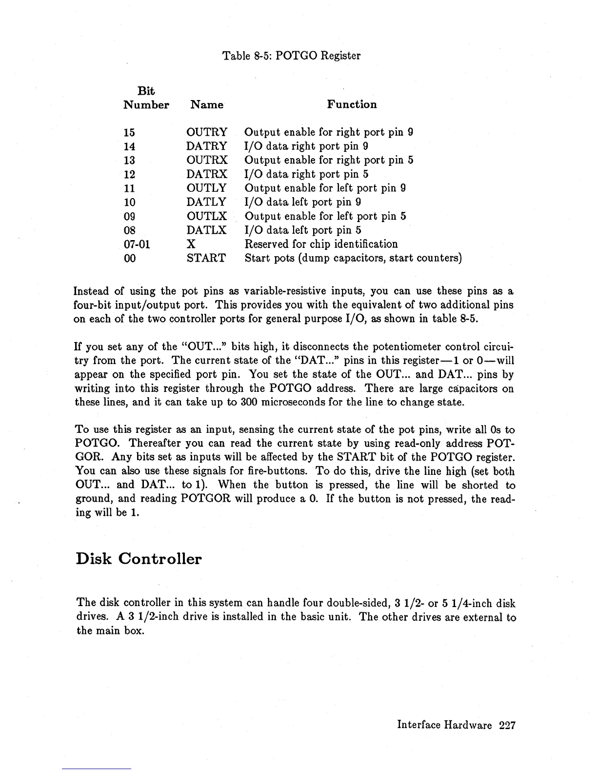
Table
8-5:
POTGO
Register
Bit
Number
Name
Function
15
OUTRY
Output
enable for right port pin 9
14
DATRY
I/O
data
right port pin 9
13
OUTRX
Output
enable for right port pin 5
12
DATRX
I/O
data
right port pin 5
11
OUTLY
Output
enable for left port pin 9
10
DATLY
I/O
data
left port pin 9
09
OUTLX
Output
enable for left port pin 5
08
DATLX
I/O
data
left port pin 5
07-01 X
Reserved for chip identification
00
START
Start
pots (dump capacitors,
start
counters)
Instead of using the pot pins as variable-resistive inputs, you can use these pins as a
four-bit
input/output
port. This provides you with the equivalent of two additional pins
on each of the two controller ports for general purpose
I/O,
as shown
in
table 8-5.
If you set any of the
"OUT
... " bits high,
it
disconnects the potentiometer control circui-
try from the port.
The
current
state
of the "DAT ... " pins in this
register-lor
O-will
appear on the specified port pin. You set the
state
of the OUT ... and DAT ... pins by
writing into this register through the
POTGO
address. There are large capacitors on
these lines, and it can take up
to
300 microseconds for the line
to
change state.
To
use this register as an input, sensing the current
state
of the pot pins, write all
Os
to
POTGO. Thereafter you can read the current state by using read-only address POT-
GOR. Any bits set as inputs will be affected by the START
bit
of the
POTGO
register.
You can also use these signals for fire-buttons.
To
do this, drive the line high (set both
OUT ... and DAT ... to 1). When the button
is
pressed, the line will be shorted to
ground, and reading
POTGOR
will produce a
O.
If
the button is
not
pressed, the read-
ing will be
1.
Disk
Controller
The
disk controller
in
this system can handle four double-sided, 3 1/2- or 5 1/4-inch disk
drives. A 3 1/2-inch drive is installed
in
the basic unit.
The
other drives are external to
the main box.
Interface Hardware
227