II
II------------------------------------~~II
IIIII
II
Mem.
Location N
Mem.
Location
N+38
111111111
~IIIIIIIII
Mem.
Location N+40
Mem.
Location N+78
II
I
II
II
II------------------------------~~III
III
I
II
Mem.
Location N+7960
Mem.
Location N+7998
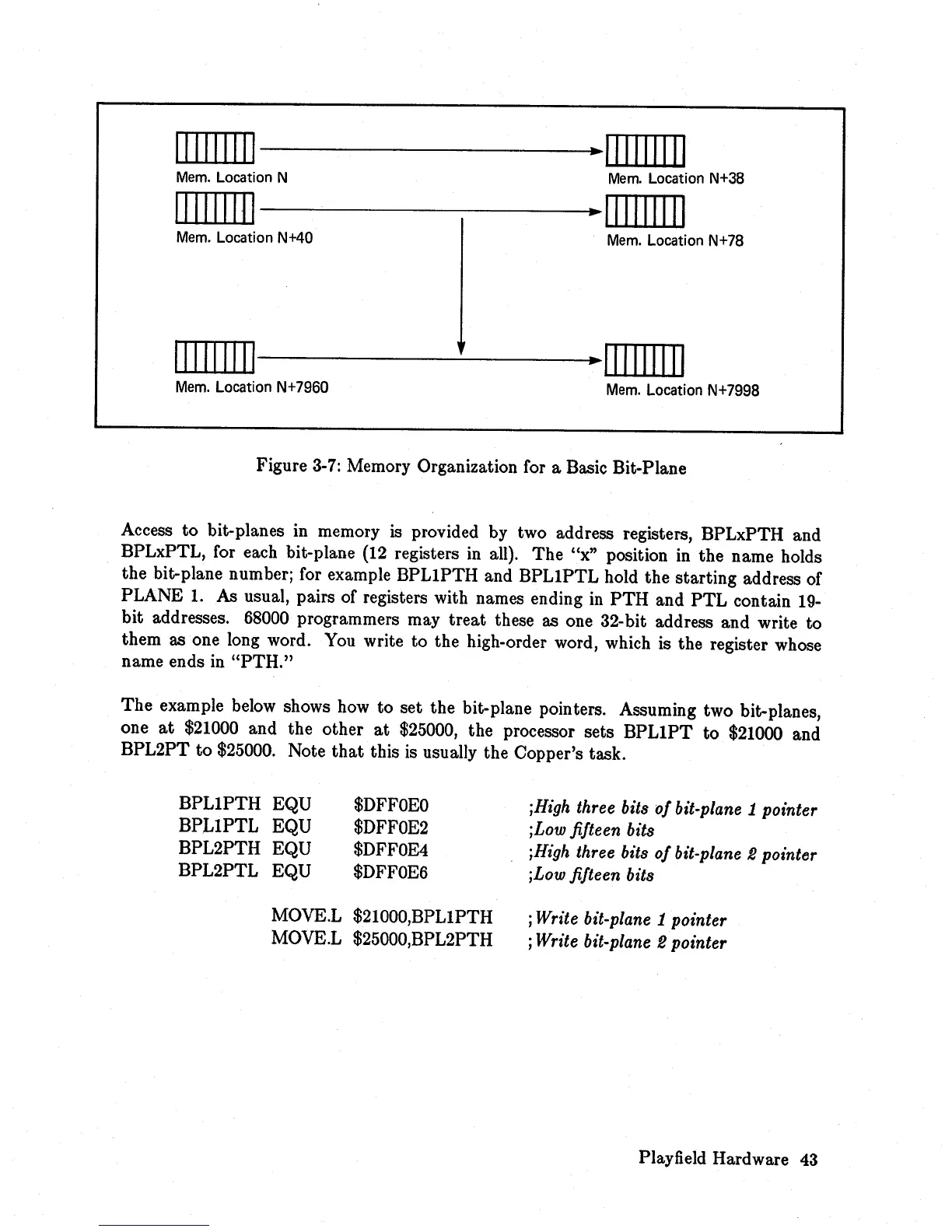
Figure 3-7: Memory Organization for a Basic Bit-Plane
Access
to
bit-planes in memory
is
provided by two address registers, BPLxPTH and
BPLxPTL, for each bit-plane
(12
registers
in
all).
The
"x" position in
the
name holds
the bit-plane number; for example
BPLIPTH
and
BPLIPTL
hold the starting address of
PLANE
1.
As usual, pairs of registers with names ending
in
PTH
and
PTL
contain
19-
bit addresses. 68000 programmers may
treat
these as one
32-
bit address and write
to
them as one long word. You write
to
the high-order word, which is the register whose
name ends in
"PTH."
The
example below shows how
to
set the bit-plane pointers. Assuming two bit-planes,
one
at
$21000 and
the
other
at
$25000, the processor sets
BPLIPT
to
$21000 and
BPL2PT
to
$25000. Note
that
this is usually the Copper's task.
BPLIPTH
EQU
BPLIPTL
EQU
BPL2PTH EQU
BPL2PTL EQU
$DFFOEO
$DFFOE2
$DFFOE4
$DFFOE6
MOVE.L $21000,BPLIPTH
MOVE.L $25000,BPL2PTH
;High three bits
of
bit-plane 1 pointer
;Low fifteen bits
;High three bits
of
bit-plane 2 pointer
;Low fifteen bits
; Write bit-plane
1 pointer
; Write bit-plane
2 pointer
Playfield Hardware 43